Arduino
- tags MicrocontrollerProgramming/codingAVR C
- Resources
- Wokwi Simulate IOT projects in browser
- ATtiny avr-1 series
- Atmega UPDI interface
- Mordern AVR
- UPDI series resistors
- SAMD11 21 Fabduino tutorial Jake
- Tutorials
- Performance
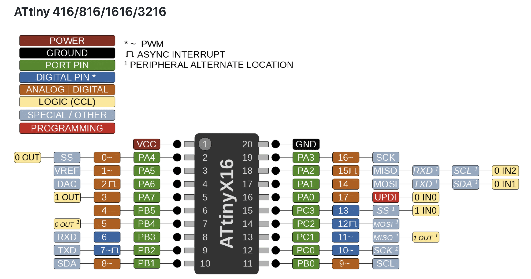
- Pinouts
- Notes
-
Arduino Interrupts
- A Hardware interrupt is triggered by something outside of the chip like a button while a Software interrupt is triggered from inside the chip like a timer.
- Within the Hardware interrupt there are two categories: External interrupts and Pin Change Interrupts.
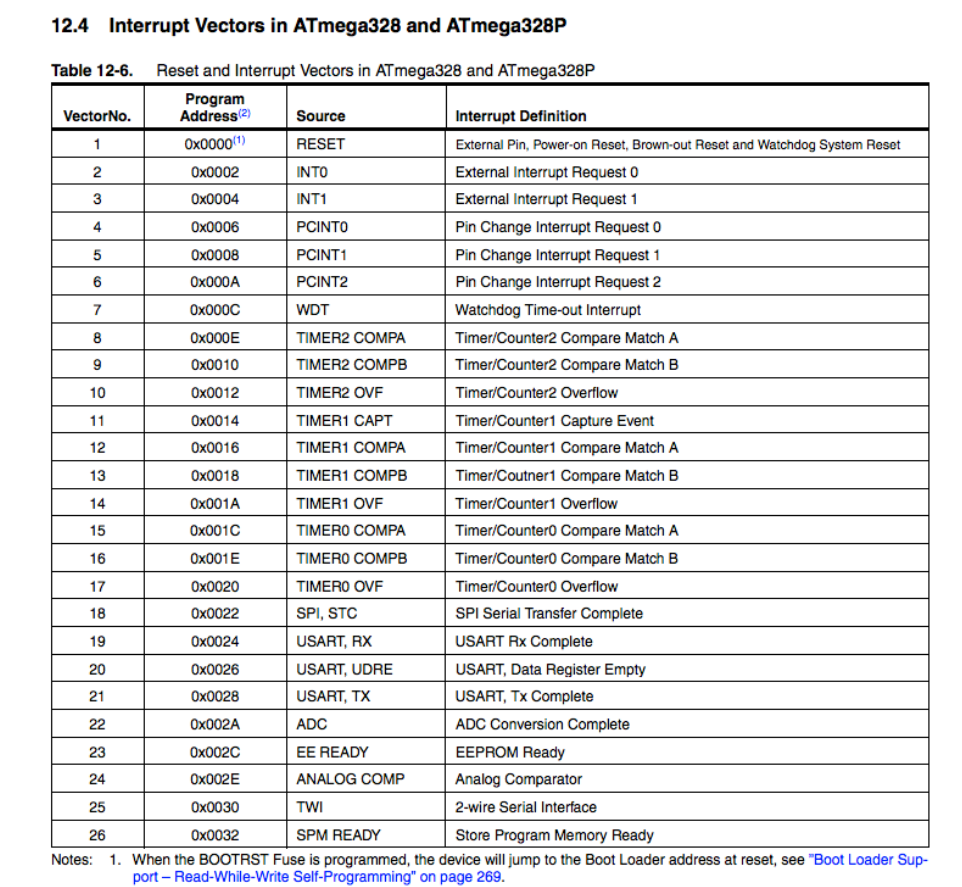
- All Hardware interrupts are external, but External Interrupts are limited to only a couple pins, while the Pin Change interrupts can occur on all input pins. For instance, on the ATMEGA328, there are two External Interrupts but 24 Pin Change Interrupts.
- If interrupts are turned on, each time an interrupt occurs it triggers an ISR (Interrupt service routine).
-
Pin change interrupts
- Each External Interrupt has its own ISR and they can be triggered independently by either a rising signal, falling signal, or by both.
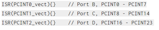
- But the **Pin Change Interrupts share an ISR between all the pins on a port **(port B, C, and D). And anytime a pin changes on that port, it calls the port’s ISR which must then decide which pin caused the interrupt. So Pin Change Interrupts are harder to use but you get the benefit of being about to use any pin.
- There are 3 steps to using Pin change interrupts, Turn on Pin Change Interrupts, Chose which pins to interrupt on, Write an ISR for those pins.
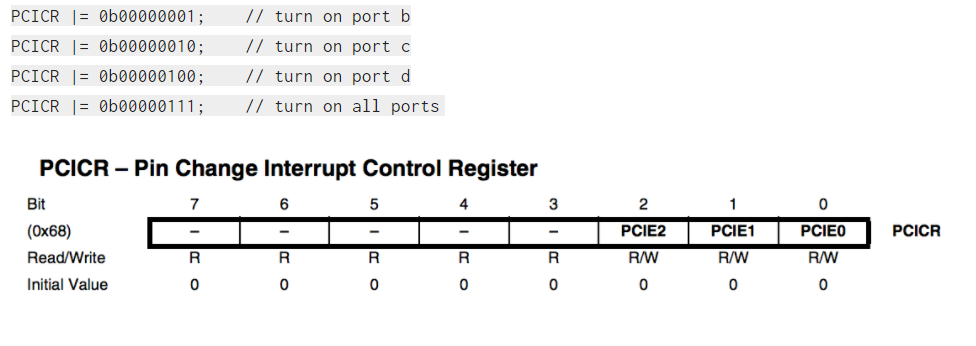
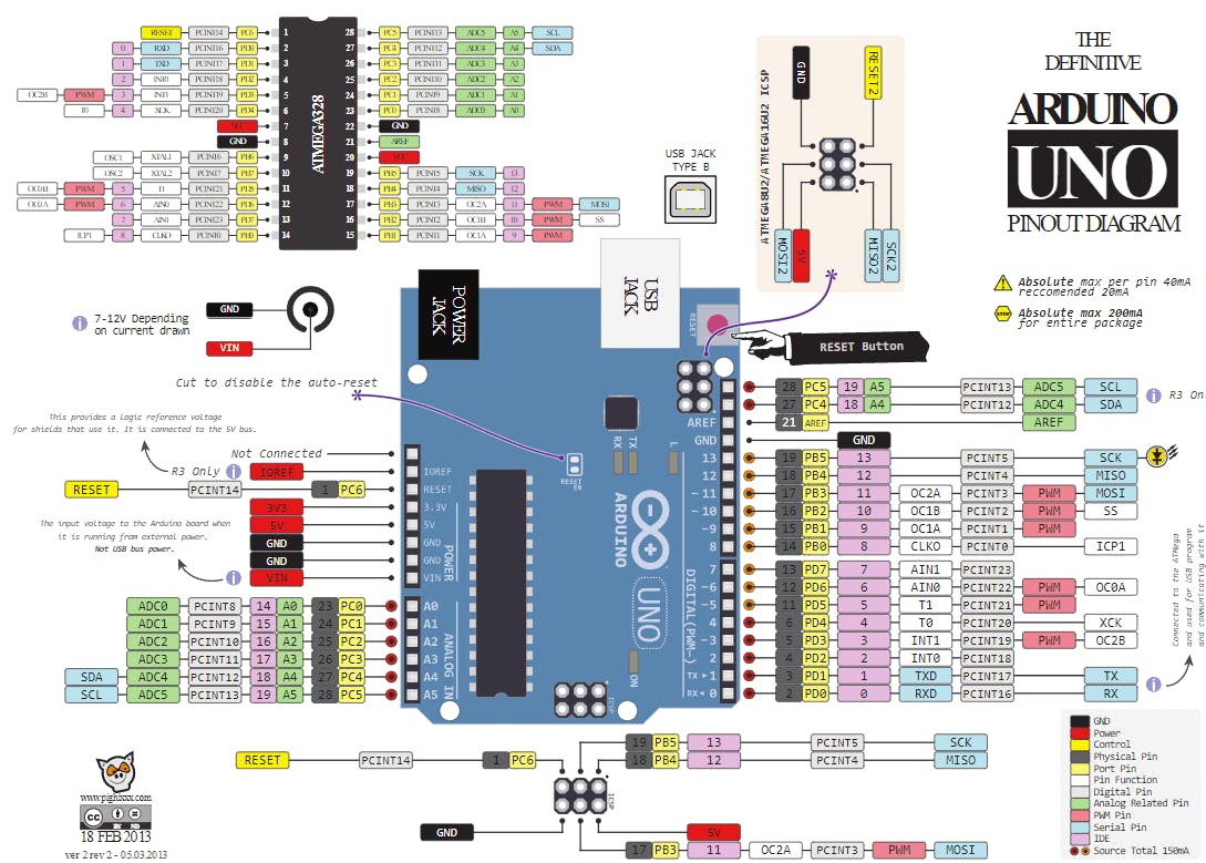
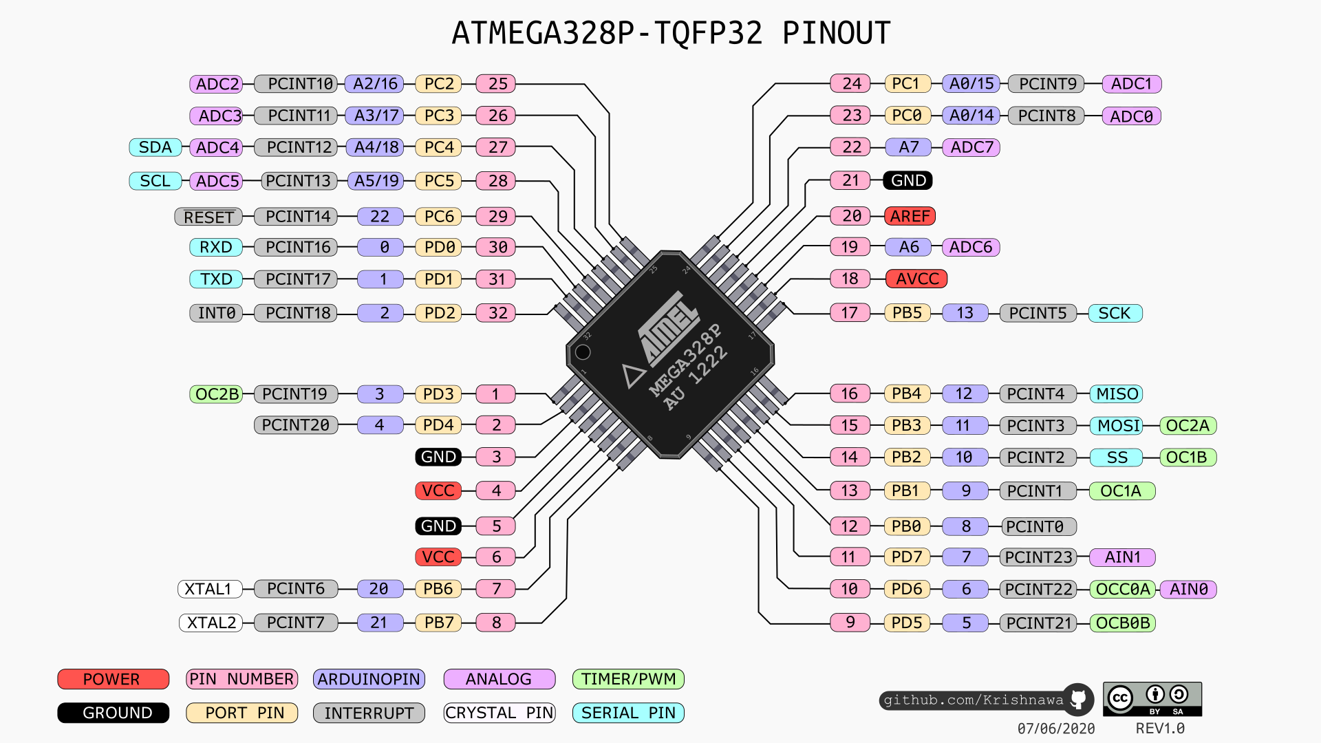
- The Pin Change Interrupts are turned on by setting certain bits in the PCICR register as seen below. Bit 0 turns on port B (PCINT0 – PCINT7), bit 1 turns on port C (PCINT8 – PCINT14), and bit 2 turns on port D (PCINT16 – PCINT23).
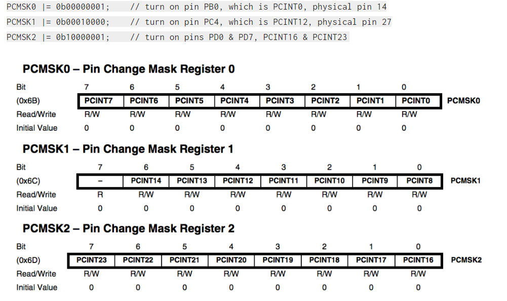
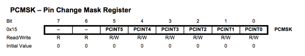
- Change on any pins in the port will trigger an interrupt, but that is true only when you set that pin in the pin change mask register PCMSK. Since the ATMEGA328 has 3 ports, it also has three masks: PCMSK0, PCMSK1, and PCMSK2.
- The last step is to write the ISR, make them short, don’t use delays, and if you are using variables make sure that they are declared as volatile. This tells the compiler that it could change any time and to reload them each time instead of optimizing it. To define the ISR, type the function below your loop.
- Example
- cli() turns interrupts off while we’re messing with them and then sei() turns them back on. Also, you should include avr/interrupt.h at the top of the sketch.
- include <avr/interrupt.h>
- volatile int value = 0;
- void setup()
- {
- cli();
-
PCICR = 0b00000011; // Enables Ports B and C Pin Change Interrupts -
PCMSK0 = 0b00000001; // PCINT0 -
PCMSK1 = 0b00001000; // PCINT11 - sei();
- Serial.begin(9600);
- }
- void loop()
- {
- Serial.println(value);
- }
- ISR(PCINT0_vect)
- {
- value++;
- }
- ISR(PCINT1_vect)
- {
- value–;
- }
-
Resetting Pin Change Interrupt Problem
- if you have enabled interrupts on a specific pin and an interrupt occurs and you do not have an ISR defined for that interrupt, the chip will execute the default ISR which in most cases activates the reset ISR and the board resets.
- first thing to note is that you can write your own default ISR if you don’t want this to happen. Just make sure you include <avr/interrupt.h> and then create a function:
- ISR(BADISR_vect)
- {
- // code to execute here
- }
-
Pin Change Interrupts on ATtiny85
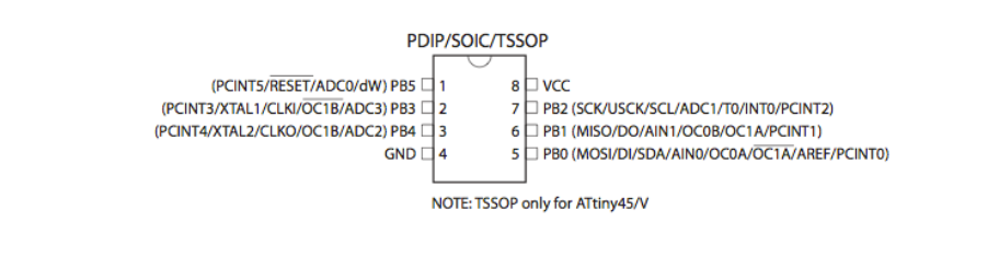
- The ATtiny85 only has one port (Port B). And instead of using the command PCICR register to turn on interrupts, we’ll use the GIMSK register.

- Bit 6 turns on External Interrupts while bit 5 turns on Pin Change Interrupts. Just put a 1 in each of the bits you want to turn on.
- we need to use a mask to say which pins we want triggering this Pin Change ISR. We do this by setting the bits in the PCMSK register.
- Bits 0 through 5 of the controller are the 6 pins that can be used for outputs. A ‘1’ in that bit means an interrupt can occur on that pin, while a 0 means it cannot. Remember that whenever any of the pins are triggered it will call the same ISR.
- Finally, you need to write the ISR function. Because there is only one port on this chip, there is only one function you need to worry about and it is called ISR(PCINT0_vect){}.
- Example
-
include <avr/interrupt.h>
- volatile int value=0;
- void setup()
- {
- }
- void loop()
- {
- }
- ISR(PCINT0_vect)
- {
- }
- {
-
include <avr/interrupt.h>
-
-
tags: #C Programming #Embedded programming Programming/codingArduino
-
Tags Arduino AVR C C Programming
-
tags: Arduino AVR C C Programming
- tags Arduino
Notes mentioning this note
Arduino
tags MicrocontrollerProgramming/codingAVR C Resources Wokwi Simulate IOT projects in browser ATtiny avr-1 series Atmega UPDI interface Mordern AVR UPDI series...
AVR C
tags: #C Programming #Embedded programming Programming/codingArduino Resources Embedded C basics AVR C Basics Human hard drive, detail explanation, register setting,...