Grinding
- tags: #Making Prototypes fab Machining
- resources
-
Traverse Cylindrical Grinding
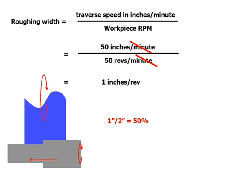
- Some part of the wheel is always cutting and the other part is doing the cleanup. Ideally you want the ratio to be somewhere around 50%. For finishing operations this ratio can be 15% cutting and the 85% finishing.
-
Centerless Grinding
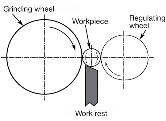
- Parts are fed between a grinding wheel and a smaller regulating wheel while resting on an angled workpiece support—a blade-like device that sits between the opposing wheels.
- During grinding, the force of the grinding wheel pushes the workpiece into the regulating wheel and against the support. The regulating wheel determines the workpiece’s rotational speed. Tilt it a few degrees and the workpiece will be pulled through the wheels and out the back of the machine, a technique known as through-feed grinding. Infeed grinding is the second technology available for centerless grinding. The regulating wheel pulls the part against a dead stop placed at the work-rest blade.
- Less grind stock for finishing is generally needed on centerless parts, as the workpiece tends to find its own center upon initial contact with the wheels. Unfortunately, this means concentricity with previously machined holes and other features can be a problem, which is one of the main disadvantages of centerless grinding. Increased setup time is another, because of the need to handle and dial-in large wheels, and special work supports might be required.
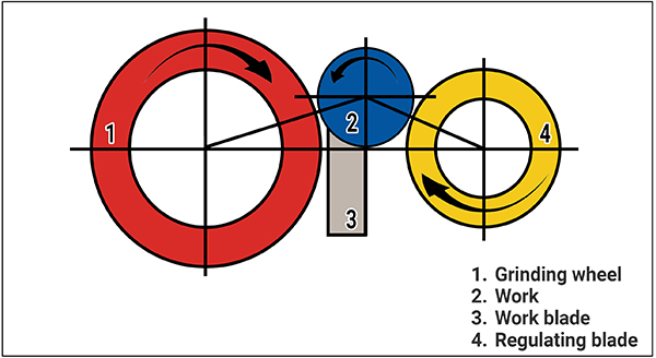
- the centerless grinder has the grinding wheel on the left, workblade in the middle and the smaller diameter regulating wheel on the right. For most applications, the centerline of the grinding wheel and regulating wheel are in the same plane, at equal heights above the machine bed.
- To achieve rounding action, the workblade must be set so that the centerline of the workpiece is above the centerline of the grinding and regulating wheels. This is a critical relationship for successful centerless grinding.
- If the workpiece rests on a flat workblade that is on center with the regulating and grinding wheels, the contact points form three sides of a square. As the part is ground in this setup, any high spot on the workpiece will shift the work slightly on the blade, allowing the grinding wheel to cut a directly opposite low spot. Over time this setup will create three lobes on the workpiece that may be dimensionally accurate but far from round.
- Setting an angled workblade so it slopes toward the regulating wheel and supports the workpiece centerline above the centerline of the regulating and grinding wheels is how the centerless operation is able to generate roundness. In this setup if a high spot comes in contact with either the blade or the regulating wheel, it does not create a directly opposite low spot because of the angle created between the centerlines of the wheels and workpiece.
- Instead of grinding a lobe shape in the workpiece, the high spot is gradually reduced by the action of the grinding wheel. So rather than creating a low spot on the periphery of the work equal to the high spot, the grinding wheel generates a proportionally smaller low spot at its contact with the workpiece.
- The angle of the workblade helps keep the workpiece in contact with and under the control of the slower rotating regulating wheel to resist any tendency to “spin up” to the speed of the grinding wheel. In some cases, a spin-up can take a workpiece from 850 rpm to near 60,000 rpm in the blink of an eye. This is not something you want to have happen.
- “One of the most common setup mistakes we see,” says Mr. Payne, “is incorrect measurement of the workpiece height. This is a critical dimension and should not be guessed.”
- A rule of thumb for setting the correct height for a workpiece that is up to 1 inch in diameter is to have one half of the workpiece diameter above the centerline of the grinding and regulating wheels. So, for a 1 inch diameter workpiece, the height should be a half inch above the wheel’s centerline. “This is the primary starting point for most centerless grinding setups
- “There are numerous ways to get this measurement,” says Mr. Payne. “Ultimately though, the machinist needs to end up with one half of the workpiece above the centerline of the wheels, resting one-third of the way down from the top of an angled workblade and against the regulating wheel. This will provide good rounding action and stable grinding conditions.”
- Centerless grinding workblade angles range from 0 to 45 degrees. For most centerless grinding applications, a top blade angle of 30 degrees seems to provide the best results. “The basic rule is the steeper the angle of the blade the faster the rounding action,” says Mr. Payne. “There are limits, however. For larger diameter and longer work, a shallower blade angle is best. Choosing 30 degrees is a good general starting point for top blade angle.”
- Also, setting the regulating wheel slow, at about 30 rpm, is a point to begin optimizing the centerless grinding process. Obviously, this regulating wheel rotation speed is dependent on work diameter and stock removal rates required. But 30 rpm is a good place to start.
- Grinding
Notes mentioning this note
Grinding
tags: #Making Prototypes fab Machining resources Abrasive speeds and feeds Ask the grinding doc video series https://www.mmsonline.com/articles/centerless-grinding-not-magic https://www.ctemag.com/news/articles/basics-centerless-grinding Lowdown on...