Encoder
- tags: CNC
- Resources
- Choosing the right Encoder Detailed
- Encoder resolution
- Absolute vs Incremental encoder
- RSI Encoder accuracy resolution and repeatability
- Jake capacitive encoder
- Jake magnetic encoder
- Capacitive absolute encoder
- SSI encoder overview
- BISS encoder overview
- Incremental encoder basics
- Ti Quadrature encoding decoding
- Efficiently reading quadrature with interrupts
- Arduino Rotary encoder debouncing ISR
- Quadrature encoder too fast Arduino
- Types
- #Magnetic rotary encoder
- Capacitive encoder
- Glass scale linear encoder(https://www.linearmotiontips.com/where-are-glass-scale-linear-encoders-used/) Sub micron precision
- Integraded Hall effect rotary encoders
- Encoder Interface
- Quadrature Decoders
- Adlink Motion Encoder interface
- Phidget High speed 4 encoder
- Designing quadrature encoder interface with spi
- Quadrature encoder counter chips
- Encoder Interfaces
- LS7166 encoder to counter #IC Chips
- LS7266R #IC Chips
- STM32 Rotary encoder Peripheral interface
- Encoder to counter interface US Digital
- Quadrature Decode with AVR attiny
- LS7366R 32bit quadrature counter#IC Chips
-
Choosing encoders
- Sources

- Characteristic of **incremental encoder **is the number of rectangular pulses per revolution. There are two channels, with a phase shift of one quarter of a pulse length. This allows determining direction of rotation and there are 4 distinct states per pulse. An encoder with 1,000 CPT (counts or pulses per turn) gives 4,000 states per turn, or a nominal resolution of 360°/4000 = 0.09°.
- Incremental encoders have a maximum frequency response which limits how rapidly it can generate pulses, this places an upper limit for the max RPM of the application Max encoder resolution = Operating Frequency x 60 / Max RPM if the encoder’s operating frequency is 125kHz and the maximum shaft speed is 1,000 RPM, the encoder ppr calculation for the maximum resolution the encoder supports is 7,500 pulses per revolution (PPR).
- Unlike incremental encoders that are push only system, **absolute encoders **are a call and response type that outputs a bit or a unique word that relates to the discrete position only when asked by the controller. Hence they are not limited by the frequency response in relation to the total pulses but by the amount of data communication required over a specific sample period, or the baud rate.
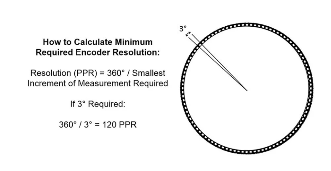
- To determine number of discrete positions required (N), first determine the smallest incremental of measurement (I) required within 360 degree rotation: N = 360 / I For example, if you require measuring down to 0.01 degrees, the resulting calculation would be N = 360 / (0.03) = 12,000 discrete positions.
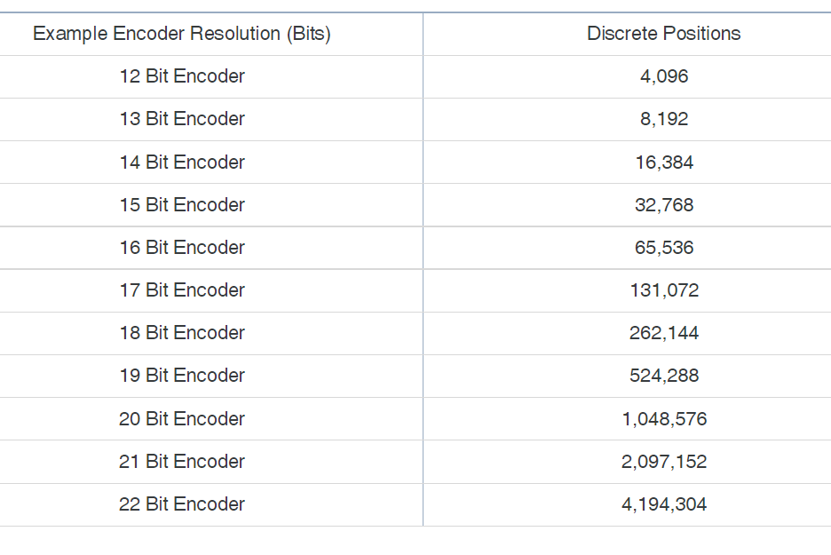
- Coded discs are patterned to produce a unique word for a specific angular/linear position, hence the resolution is measured in bits which give 2^n number of positions.
- Baud rate is unique for each encoder communication protocol and varies by cable length. Generally, baud rates decrease as cable length increases.
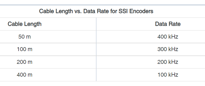 SSI, a long cable run and a high clock frequency can disturb the data signal due to propagation delay of the signals over copper wires and it is necessary to reduce the clock frequency or the cable length for the system to work.
 - Resolution gives the nominal accuracy, some movement may be shorter than the pulse count, measured position deviates from the real position in a periodic way over one motor revolution.
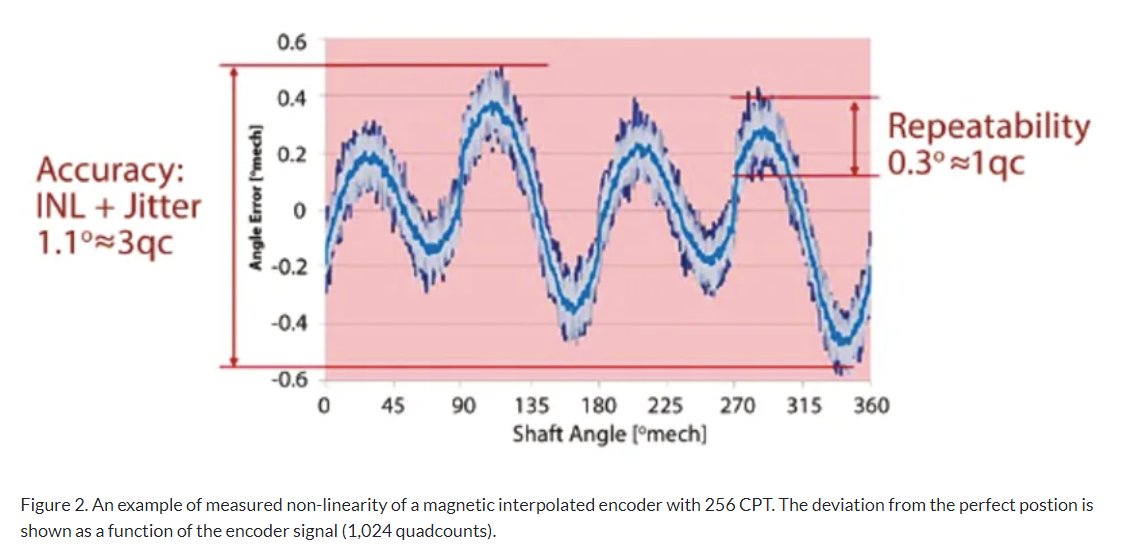
- The maximum deviation (peak to peak) is called integrated non-linearity (INL). INL is important in applications that require absolute position accuracy. Repeatability is not affected by INL, but is rather a question of signal jitter, and typically amounts to less than one state.
- Line drivers are recommended for transmission over long lines and for better signal quality. For positioning, a line driver is important to avoid missing encoder pulses. Line drivers generate inverted signals (A, B, I) for each channel (A, B, I). Each signal pair is transmitted together and the difference is evaluated, thus filtering out any electromagnetic interference during signal transmission.
- Encoders need a minimum supply voltage. On long encoder lines, the line resistance and the corresponding voltage drop can be an issue. That’s why it’s important to check the cable cross-section and the supply voltage.
- Rule 1: Encoder for Positioning — A good recommendation is to select an encoder with a number of pulses higher than 360° divided by the required angular position accuracy; in other words, a number of states that is four to ten times higher. For positioning, select an encoder with a line driver (differential signal).
- Rule 2: Encoder for High-Precision Positioning — Select optical encoders with a line driver for high-precision positioning. They have a higher resolution, less jitter, and a lower INL than interpolated magnetic encoders.
- Rule 3: Encoder for Positioning with Mechanics — Select a magnetic encoder with a line driver and with a moderate or low number of states. The mechanical reduction will increase the resolution. Due to the mechanical play, the system will not be able to benefit from a high-precision optical encoder.
- Rule 4: Encoder for High-Speed Control (> 500 RPM) — Select an encoder with a moderate or low number of states and a sufficiently high maximum speed rating. There is usually not a need for a high-precision optical encoder. A good rule of thumb that is usually sufficient for most applications is (speed in RPM) × (encoder resolution in CPT) > 100,000.
- Rule 5: Encoder for Low-Speed Control ()
- tags Encoder Microcontroller
Notes mentioning this note
Applied Robotic Stanford CS235
tags: Robotics #Making Prototypes Source CS235 Youtube What makes a good robot designer is the attention to the details. Every...
Encoder
tags: CNC Resources Choosing the right Encoder Detailed Encoder resolution Absolute vs Incremental encoder RSI Encoder accuracy resolution and repeatability...
Quadrature Decoders
tags Encoder Microcontroller Resources Quadrature decoder 74HC74 Dual Flip flop Used for decoding, will not work in low speed and...
STM32
tags ElectronicsMicrocontroller Resources The world of STM32 Jeelabs Encoder STM32 Timer encoder mode Interface rotary encoder pheripheral Quadrature encoder with...