Applied Robotic Stanford CS235
- tags: Robotics #Making Prototypes
- Source
- What makes a good robot designer is the attention to the details. Every tiny detail and related effects needs to be considered.
-
Best practices
- Use shims and dowel to align parts and if they are not needed after everything is bolted down, make them such that they are removable after aligning.
-
Bearing
- Always look at the shaft tolerance when ordering ABEC bearings because a difference of 20 Micros is enough to make the shaft not go in.
- Never press bearings into shafts as you will put pop marks on the inner or outer race, which will cause cyclic loads and the bearing will fail early.
- When using shims on bearings its never good to press metal on metal without some kind of spring in the system, like when using two bearings and using a shim to separate them.
- Imperial bearings are almost 4 times as strong as metric bearings for the same size.
- Flanged bearings are expensive than regular ones. For thin section bearings there are limited flanged types, get around the problem by using retaining ring bearings, which have a slot cut on them and a retaining ring is pressed in. acts similar to a flange and much cheaper.
- Larger diameter bearings are turntable bearings, they are cheap but not accurate, also works for missiles, but expensive version.
- shims are precision spacers, but washers are not.
- G6 shaft tolerances are always negative as they will be smaller than the bearing. Always look for good tolerance shafts that are within budget, to reduce the shaft size, put 400 grit sand paper and take a couple of pass with a drill.
-
Gears
- Gear efficieny
- Spur 98-99%, Helical 98-99% if they are parallel, if orthogonal(skew, crossed) 70-98%, Herringbone (double helical gear) 98-99%, worm gear 20-98%
- Idler gears only changes the direction and the distance between gears.
- Backlash
-
Spur gear
- The pitch or the module of the gears should match in order for the transmission to work.
- In compound gears the smaller gear on top of the larger one will experience a higher contact force or tooth loading. Here the limiting factor is the material property, so we want to use cheaper plastic gears when they allow for it, but go for metal or stronger materials when the tooth loading gets bigger.
-
Worm gear
- Worm gear set is two parts, the worm and the worm gear. They have orthogonal shafts.
- The worm has only one tooth, and the gear can range form 10 to 500, so the gear ratio is very high.
- But the interface is a sliding contact, which means loss of efficiency. They are not usually back drivable but can be like windshield wipers. The reason worm gears are not back drivable is because they have low efficiency.
-
Helical gears
- Why use helical, because they have a gradual sliding contact, less noise and smoother operation.
- They are available in both right and left handed. Two configurations for the gears is in parallel or orthogonal.
- E= B1 + B2 where E is the angle between the shaft and B1 and B2 are the Helix angle of the two gears, its usually 45 deg but it doesn’t have to be. Lets say right handed is positive and left handed is negative. If we have two of the same gear, then we can run them orthogonal to each other, but if we have one with a right handed and other with a left handed thread then we can run them in parallel.
-
Bevel Gears
- Bevel gears are section of a right circular cone and the axis meet at a common point. Miter gears are subset of bevel gears, they are always one to one and at 90 degs.
- Gear efficieny
-
Screws
- Screws are not precision instruments, they are not perpendicular and usually undersized, should not be used for precise alignment. Screws are better in tension than compression.
- Use dowel pins for alignment and screws for force.
- For harder materials like aluminum and steel, don’t put more than 2 holes on a face, you will over constrain it. For softer materials, this is good as the small deviations will cancel each other out. Its good to evenly space out screws to make sure the plastic is perfectly flat.
- Standard term for bolts around a flange is Bolt circle BC, the diameter of the center of all the bolt holes. 3 holes evenly spaced with a 20mm BC.
- Three types of taps, only difference is the taper at the tip. Taper helps to self-align with the hole, but in the case of a blind hole (pocket) The Threads will not form all the way to the bottom. This is where you use a plug type tap which has a square tip.
- The Reamer is only for precision holes, like reboring the engine cylinder. Always go for the drill size just small of the reamer. like for 4mm use 3.9mm drill. The standard increment is one thousands of an inch.
-
Friction Drive
- Friction drives are great when you need to transmit a** set amount of force in a simple manner. They are inherently safe, and act like a mechanical fuse, as any overload causes the drives to slip without damage. The power transmitted depends on the **friction coefficient and the preload force. They can be used for either actuation or sensing.
- Frictional coefficient is a property of materials, and the mating surface conditions.
- If the drive slips, need some provision to detect the slip and rehome the machine.
- The main disadvantage is it loads your bearings very much because of the preload.
- A way to make the drive** back drivable** is to set the friction torque above the back drive torque.
- Good materials for friction drive have a high coefficient of friction and low **Loss coefficient. When you take an elastic material and you load it cyclically there will be an **elastic hysteresis, and you lose energy in that. The lower the loss coefficient, the less energy lost.
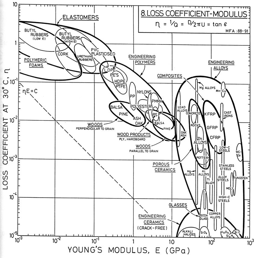
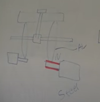
- Some of the best materials for friction drives are Aluminum on aluminum, or steel on steel.
-
Differential Drive
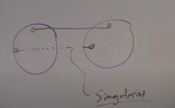
- Friction based differentials are great for robot actuators, human wrist is roll, pitch yaw. Common robot actuators are roll, pitch, roll. That’s a singularity but its also cheap to make with a differential. The differential gives us **intersecting roll pitch axes **which makes our math easier.
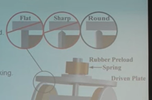
- We want the interface to make a point contact and the only way to do that mathematically is by a round shape.
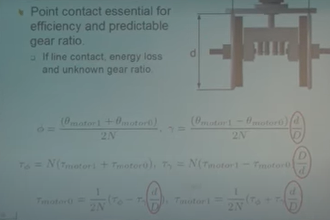
- Phi is pitch and gamma is roll.
-
Belt Drive
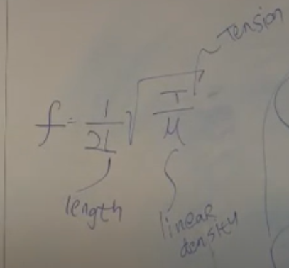
- Belts are friction drives that can span distances. Different types include, v belt, flat belt, round belt, timing belt. open loop, and closed loop belts are determined by their pitch length.
- They are composed of a rubber material urethane, neoprene, and a tensile member usually stainless steel, fiber glass.
- Belts like cables have resonant frequency, if you try to operate above the resonant frequency it will excite the system and worst case, cause it to break apart. Low resonant frequency occurs when you have a long line with a mass in the middle.
- Resonance is also bad when there is unpredicted shock loading on the system. like when it hits an end stop or if someone kicks it. The loading will be a step function and that’s bad because it excites all the frequencies in the system.
- Belts vs cables of the same size, belts have lower frequency because the rubber damps out the vibrations.
- Use track rollers as idlers to tension the belt. Using idlers will reduce the free length and boost the resonant frequency.
- Belts have a max power that they can transmit, never exceed that also they have a working tension that is the pretension that is needed to transmit power.
- The main energy loss is the hysteretic energy loss from squishing and un squishing the rubber.
- A big problem with belts is that they pre-load the shafts more than gears. This needs proper bearing selection to match loads to fixtures.
- Backlash for belts are very nominal and show up only under large loads. The load has to break the friction between the surface, and then the teeth will deform before slipping. They are not present under normal operation.
- Failure modes,
- If not tensioned properly, the belt skips over the pulley.
- If tensioned properly, then with much force the tooth will shear off. This is tooth shear.
- Fatigue, where the cyclic stretching and unloading of the tension member results in failure. To reduce effect of fatigue, its better to not cycle between tension and compression, ie if possible constrain the belt in one direction by putting all the pulleys on one side.
- Two types of tooth, Trapezoidal and HTD (high torque Drive). Trapezoidal has greater backlash.
- A neat technology is Helical Offset tooth synchronous timing belts. which have helical sliding contact and herringbone type tooth which prevent belt wander and can be operated without flanges.
-
Capstan Equation
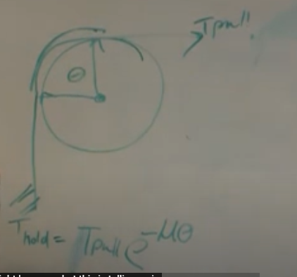
- For stainless steel belt and aluminum pulley, you only need about 3-4 wraps until it wont come off.
-
Motors
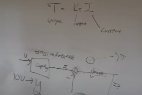
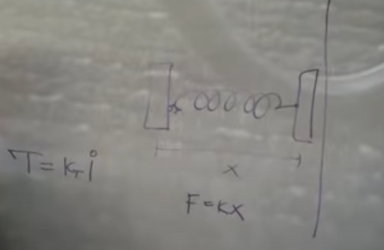
- For motors the Torque output T=Kt *I Kt is the motor constant. Which depends on the winding geometry, number of turns, etc.
- For DC brushed motors, the cheaper ones use graphite brushes, which have high friction and high wear. The high end motors like maxon uses precious metal brushes which have low friction and last a long time. This is important in haptics as the frictional forces between the brushes will limit the minimum force that can be applied by the motor.
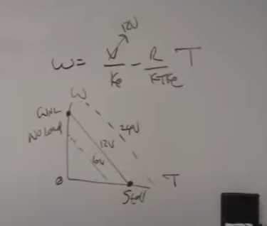
- For steady state this is the line a DC motor behaves. The bottom right condition is the stall and the top left is the no load speed. Keep in mind that **every time your motor starts up, its starting form the stall condition. **So spec current to meet the stall condition.
- The way to control a motor is, the control loop sends a voltage to the motor amplifier. The amplifier receives the voltage and turns it into current through something called Transconductance which is how the ratio of current change to the voltage change in an electronic system. Which sets up a closed loop current in the motor coil, with the set point given by the voltage applied.
- This is the easiest way to drive motors but nobody does this. All the industrial guys use Voltage drives.
- The two main types of control used are
- Force control T=Kt*I you need special current sources for them.
- Voltage drives, you use PWM to generate voltage output to command motors.
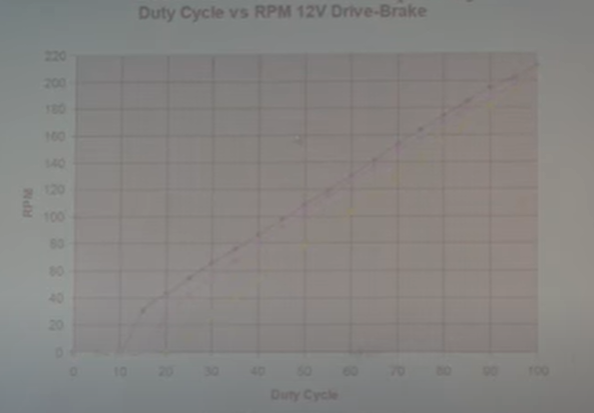
- Duty cycle of the PWM vs RPM of the motor. running at higher frequency 20Khz is better as it gives better linear relationship of the PWM with RPM. There will always be a dead band near the low end of the duty cycle.
- The time it takes current to go from 0 to 63.2% is the time constant T=L/R, L inductance, R Resistance.
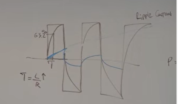
- When we are doing force control with a DC motor by controlling the current, we want to keep the motor current in a stable position. The** time constant defines how fast the current rises** in the motor. Any current over the mean value is wasted as I^2R heating losses. So if we want smooth control of current we need to increase the time constant. For this we will use inductors in series with the motor terminals.
- This will smooth the current wave forms and keep the motor current near the mean value.
- Everyone who does haptics uses ‘RE’ series maxon motors and Copley amps. **The Copley amps is a closed loop current controller, It will explode if we don’t give a time constant within the bands they accept. The problem is that for similar torque ranges the maxon motors will have very low inductance even for the same resistance. **
- Two things can happen if you plug your maxon motor to your Copley amps,
-
- The motor will heat up fast as the time constant is very low and there will be ripple currents.
-
- The current control in the copley explodes and the motor starts spinning infinetly.
-
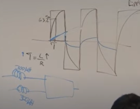
- The solution is to use two inductors in series, typically 300mH each.
- Practically you are slowing down your electrical dynamics so that you are stable in torque speed region, after that you have the rest to work on your servo loop.
- Maxon motor RE series have part numbers form RE 40/30/10 the number defines the outer diameter. Careful when using a RE-10 the smaller the motor, the smaller the wires and the resistance goes up. That means the 300mH will not be enough and you will burn the motor instantly.
- Never design your parts around the CAD models provided by any manufacturer. The bible is the spec sheet provided with the part.
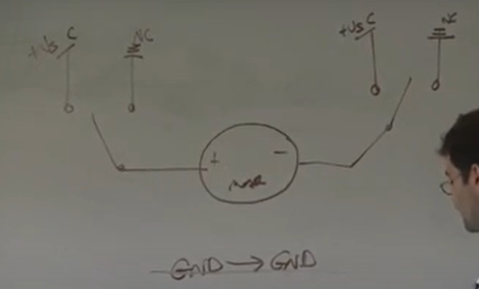
- An easy way to run DC motors manually get SPDT single pole dual throw switch. They are normally connected to the NC side. when you press one, you connect ground to Vs and vice versa. when you press both nothing happens as its either connected to ground on both side or Vs.
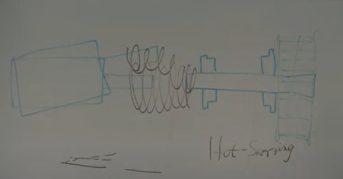
- Reasons to use a flexible shaft coupling,
- You don’t want any radial loading on the motor.
- If you put the pulley on the motor then if you want to take off the encoder and motor then you will have to remove your whole belt assembly.
- Takes ups the angular and axial misalignment.
- With this method you can **Hot swap **the motor, say an RE 30 was not big enough, then you remove the motor and put an RE40 without disturbing the rest of the setup.
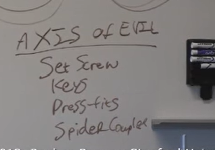
- Don’t use spider couplers, good helical couplers are best.
- Don’t get the ones with set screws, once you tighten and run the motor for 5 mins they will back out and fall into your machine. If you are unlucky they will get in between your gear and the slides.
- For a given size set screws have a higher torque transmitting capacity than clamps. If the manufacturer does not list the max torque for the clamps, don’t buy them. If you need a small coupler and high torque capacity, use a set screw.
-
Motor Cogging
- DC motors have discrete positions where are stable and it takes a small amount of torque to take them out of these positions.
- Cheap motors will have a ferrous core with high magnetic permeability and over time develop a slight magnetic field. This interacts with the stators magnetic field causing cogging.
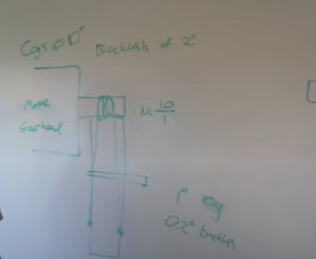
- Gear and cable transmission **are not only for speed reduction, you can use them **effectively to take the bad performance out of a motor.
- Say you want a 100:1 gear ratio, its better to split it into two parts, say a compact 10:1 gear on the motor and a compact 10:1 capstan drive, this will take out the backlash in the gears and you will have higher resolution.
- The larger gearbox would have say 2deg of backlash, but putting a 10:1 capstan on top of it effectively reduces the backlash to 0.2deg.
- The cleanest way to get more torque is to have bigger motors.
- Make sure that you are not using the motor near the peak currents as you will torch them. Maxon provides specs for if you use the motor near stall, how long you have to let it cool before you can use it again.
- Motors have max axial and radial forces, do not exceed that. Never pressfit onto the motor shaft, they are difficult to get on and remove. All the details of how you put the pulleys matters.
-
Stepper Motor
- Lin engineering custom stepper and BLDC motors
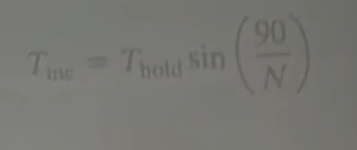
- Tinc is the incremental torque, Thold max torque and the N is the micro steps. So full step N is 1 and sin(90) is 1. If we microstep to 16 the only torque we have available is down to 9.85%
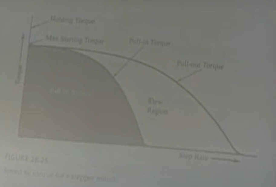
- Torque vs slew rate(velocity) two main curves, pull in torque and pull out torque.
- The pull in torque region any torque and velocity is possible. The pull out torque is the maximum it can give without skipping steps. The slew region is where the torque and speed are attainable but not instantaneously, there is starting and stopping inertia.
- Why does the torque curve fall off? well its a giant inductor and the faster we move the less happy the inductor is and you will not be able to achieve full current, running at higher voltages can help decrease the rise time.
-
Gear motor
- Spur gear motors usually have off-center axis, planetary gear motors have large power densities.
- Reflected inertia of gear motor is N^2. Jo = N^2 Ji, Jo is the inertia at output.
- The friction at the output Fo = N*Finout, where N is the gear ratio.
- Exponential decrease function when plotting gear ratio and back drivability.
-
Slip Ring
- For when you want to transfer signals and power through a continuous rotating joint.

- Poor man’s slip ring is an Audio jack with multiple channels in them. The problem with them is the electrical noise, as you are scrapping metal on metal, there is some wired capacitive noise that gets in, its ok for driving motors and high power devices but low voltage signals for sensors will kill them.
-
Springs
- Sources - Leesprings.com
- Types - compression, extension, torsion, Conical springs (have interesting stiffness to deflection properties)
- When designing with springs you want to make sure that you secure it, in the event it comes off, you don’t want it to take out someone’s eye. Larger springs store a lot of energy and you need to design ways to mount and secure them.
- You can put springs in series with the transmission to reduce the impact stress.
- One way to use springs is to do Force control when you can only do position control of the motor. Like cheap RC servo.
- When you are putting springs in series do want low force or floppy springs, which give more encoder resolution as you have to move a large amount to get the same force. Stiffer springs with need high resolution encoders.
- The problem with floppy springs is that it lowers the resonant frequency and the less bandwidth you have to work with.
- If you are using materials as springs then you need to test and characterize them measure the force and the deflection.
- Stiffening springs, the harder you push the stiffer the spring gets. One place to use this is in a robot aim where you want the arm to be floppy when people are around it and when its being worked on. but after that you want to move really fast in auto mode and do repetitive tasks as fast as possible. In the second case you need it to be stiff.
- One way to do that it to put two springs in parallel in the cable transmission and by controlling the effective length of the cable, you can deflect the springs by set amounts to change the stiffness and thereby use the same mechanism.
- You can use springs in parallel to increase the factor of safety as the fatigue life on these are not great and you want to minimize the chance of all of them breaking and the robot coming crashing down. Also the fatigue life on smaller springs are much greater than larger springs.
- You can use pneumatics are springs,
- The main advantage is that you can use them not as the actual actuator, but as the transmission. Say you want to build a robot and you want some inline compliance, you don’t have to use traditional means, this can be both the cable and the spring, you can route them through difficult paths. Then you get the transmission and the compliance for free. To increase the stiffness in the pneumatic cylinder, increase the pressure. You can set how stiff it is.
- Pneumatics as transmission you don’t have to keep pumping air into it and they are fairly linear in terms of force and deflection till the very end where it goes up exponentially.
- A good reason to use gas springs are they are light and when they fail, they don’t fail rapidly they just loose pressure and you can recharge or replace them.
- End stops, Misumi, part Gel MRF. When using endstops its a good idea to make them in parallel. One as soft stop with some energy absorbing material and the other one a stiff material that sets the limit the robot can move.
- Its usual practice to put a sensor both an optical and magnetic just before the end stop and wire them to the motor controller and send a software flag into the PC which shuts everything off.
- Energy in a linear spring is Kx^2. For a non linear spring take the force deflection curve and take the area under the curve.
-
Magnets
- Source: KJmagnets
- Magnets are a compact high power dense non linear spring. Non linear as in they do not obey Hooke’s law (F=Kx). In magnets the force is proportional to Cubic function.
- One great function is to use them as end stops, they are compact and can be assumed to have infinite force as they get closer. In essence, they provide a smooth ramp and prevent the surfaces from colliding.
-
Flexure
- Flexures are usually thin as we want to minimize the spring force for moving them. The thinner the cross-section is the more certain we can estimate the center of rotation.
- If you use a single flexure, the center of pivot may not be accurately determined. But if we use them in pairs then the instabilities tend to cancel themselves out.
- Plastic turning white because of loads is called crazing, keep creep in mind for static loads over long times.
-
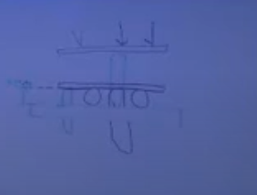
Capstan Cable Drive
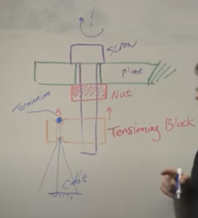
- Terminating cables with tension block and adjustment screw. The notches on the adjustment screw is so that when the fleet angle changes the cable does not scrape against the edges.
- The distance provision for the tension block is dependent on 2 factors. The first is you need enough clearance to get the cable over the flanges in the pulley. The second is the error in cutting and crimping the ends of the cable.
- Need to be careful when clamping cables as any misalignment needs to be accounted for and provisioned. When squishing cables with a nut and washer the ends of the washer can dig into the cable and cut it after some use.
- The main thing when designing with cables is assemblability, can you put it together by yourself. How difficult is it to adjust the tension, have you made provisions for misalignment?
- Bike chains and Ball chain are also cable drives.
-
Unusual Transmission
- When you have a weird geometry and want to transfer power to the system.
-
Push Pull Cable Drive
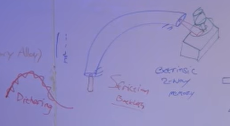
- The two main parts are the cable and sheath. You ground both the ends of the sheath and drive the cable back and forth. There will be some backlash in the system as the cable bends.
- Energy is lost in friction between the cable and the sheath, use **Teflon tubing ** use core of Nitinol. Nitinol is half Nickle and half titanium.
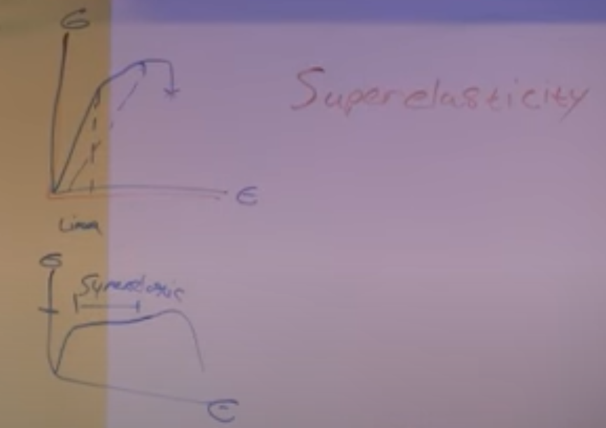
- First reason to use nitinol is Super elasticity this means for fairly low stresses you can take nitinol and bend them very much. This is important as the cable system is taking torturous bends throughout the system.
- The ways in which materials fail are because of Tensile, compressive, shear, flexural loads. You will never reach the compressive strength limit as buckling will happen.
- Buckling is a material and geometric phenomenon.
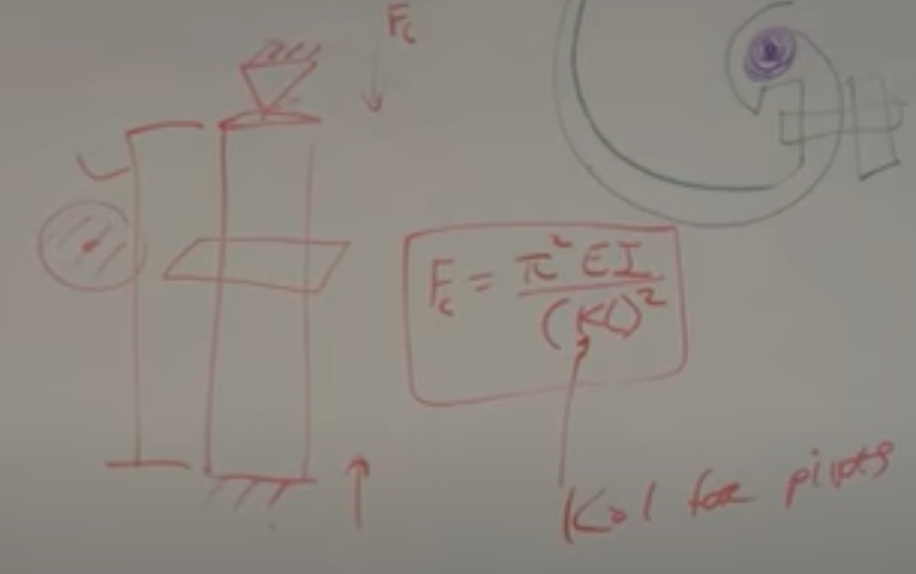
- Buckling Equation where Fc is the critical force, E is the young’s modulus, I is the area moment of inertia, L is the free length, K is a constant for end conditions, from 0.5 to 2 for pivots K is 1.
- In push-pull systems there is significant lag, as the initial force will have to buildup to overcome friction, then it will take up the backlash then only will the output move. The static friction is higher than the dynamic, so one way to take out the nonlinearities and reduce the force required is to always keep the core moving, back and forth. This is called Dithering.
- So when we want to move it, its like a sine wave over a carrier wave, the control will always keep the cable moving back and forth and large motions are carried over.
- The same minimum bend radius for braided steel cables do not work well for nitinol as it is a single core and even though it has super elasticity it will kink and break.
-
Flexible shaft couplings
- These are flexible shafts that can transmit torque. They are very rigid in torsion but not rigid flexuraly, so you can bend it around.
- The main problem with it is that it acts like a torsional spring. There isn’t backlash but there is windup.
- They are rated for the power, lower speed higher torque. P= TW. When you bend it the torsional rigidity goes down considerably.
-
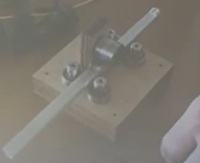
Universal Joints
- Universal joints have two axis of freedom, pitch and yaw. They are meant to transmit torque unlike spherical joints which have 3 degrees of freedom and meant for free rotation.
- They have pins which allow for motion, but pins have backlash as you need clearance to operate.
-
Control System
- Feedback systems will rely on the measurement of the sensor to find the error and correct for it. Feed forward (openloop)will go without measuring and then modify the signal based on where you got.
-
Position sensor
- Two types of position sensors are Analog and digital,
- Potentiometer is an analog voltage divider, that gives a voltage based on the position. Linear potentiometers are used in audio, common known as Fader pots.
- Hall Sensor is an analog device used to sense the presence of magnetic fields.
-
Encoder
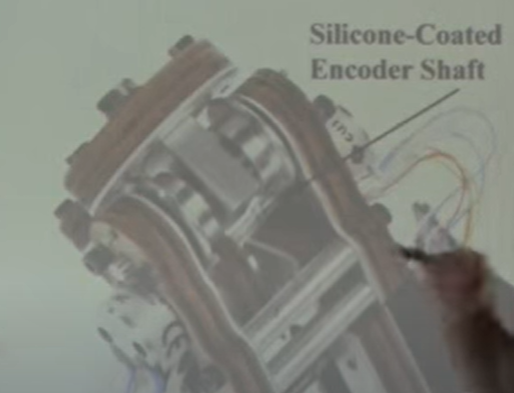
- Never use encoder shafts for any load bearing application.
- Fit silicone tubing over encoder shafts to increase friction and have lower normal force for friction coupling. This works because there is a big difference between transmitting motion and transmitting force.
- Optical Incremental encoder use a light that shines through a coded disc
- Never use adhesive backed encoder, it will fall off and mess up the threads on the motor.
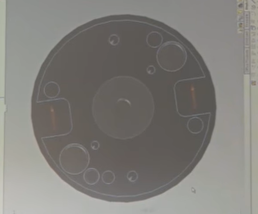
- Use a cone shaped centering tool to precisely locate the encoder plate before you tighten all the screws. This ensures that the encoder is concentric and will not skip counts.

- Encoder with a flexure spring plate, this can handle some degree of axial misalignment and get better results.
- Decoding encoders, first check the CPR, then put the line on a scope to check for noise, check to see if there are debris in the encoder wheel, and is installed properly.
- From a controls perspective its easier to put the encoder in the back of the motor, if you put the encoder at the end, in a mass spring damper system say like with a belt, then a gear, then the motor. We want to keep the relative order to two or below.
- Two encoders with a spring in between, their relative positions gives the displacement which gives the force, Force control with position control.
- For precise and large robots they usually have two encoder, one incremental and one absolute and if there is a large deviation between the two, it shuts off the robot. Why two? Absolute encoders are large and expensive.
- If you are using just an incremental encoder and you want to home the robot, how do you know which way to turn?
- You get a cheap slot sensor over the encoder disk and cover half the index wheel with the shot. So now you have binary yes or no to go CW/CCW. The reason we are not using the slot as the index is because its not accurate as the index in the encoder.
- Another way to do this would be with a 3D accelerometer, assuming your robot is right side up, you can always know where gravity is and back calculate all the inverse kinematics to get to the orientation. The problem is the base needs to be stable during the startup or the accel will not give right values.
-
Analog vs Digital
- Even if you have the best potentiometer, you would not want to use it as it is an analog device, and you will have to interface it with the computer. This gives chance for noise to get into the system.
-
Incremental Encoder
- There are two types you can get, Single ended and Differential output.

- A single ended is referenced to ground, this is simple but there is a **chance for noise **to get into the system, especially when large motors are present.
- A Differential type subtracts Hi from Low, so that if there is noise, it will be present in both lines and will get subtracted out. Higher voltages are less susceptible to random noise. This will only work if **both the encoder wires are close by **such that noise is same in both. Like twisted pair cables.
- There are high end encoders which have a sine output, called as a sine encoder These have the high and low tick points but the** intermediate curve is an analog sine wave**, whose values with reference to a lookup table can give resolution within the two ticks. The problem is that, to make this work you need an interpolation board that can talk with the computer. Know what a sine wave encoder is and don’t use them.
-
Potentiometer for linear
- There are string pots/potentiometers, which allow you to wrap a string around a pot and use it for linear measurement. These are strings on a constant force spring which you can use like a tape measure.
-
Interfacing with the computer
- When working with windows, using Qt to create GUI for robots are best. QWT is an extension to Qt and offers a bunch of libraries for plotting, knobs and switches you can use to interface with the robot.
- You need a PCI/PCIe DAC card, from national instruments for windows. USB DAC puck less capable, more compatible.
- LabVIEW is to engineers who can’t code.
- Data Acquisition Card (DAQ) cards have some DI/DO, AI/AO, counters, PWM. For encoders its better to get DAQ cards with just counters on them like the PCI6602 It can handle 8 encoders. The only job of the board is to count the signals. If you are using an Arduino to count the encoders, then you will be using interrupts to count them. With the DAQ card, you can pull the data when needed.
- All counters do is count a square wave, If you are using the Digital In, then the programmer is responsible for keeping count.
- For general purpose work, buy an Analog IN/ Analog out and a counter card. This comes with a lot of digital outputs and you can build anything you want.
- Using microcontroller, is you don’t want to close the loop in the MCU, connect it to the computer, setup a serial communication and use it like a DAC card.
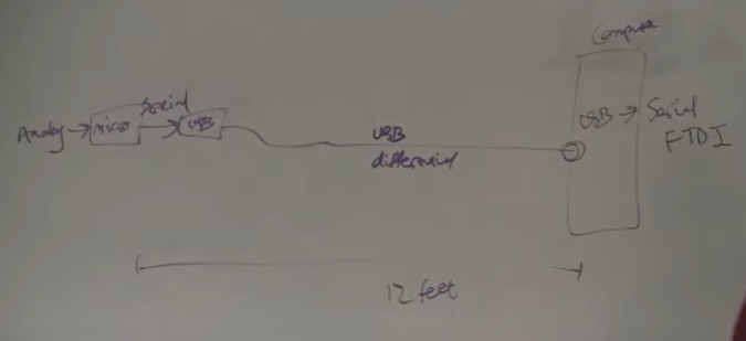
- USB provides differential signal, which is immune to noise. Its better to convert analog signals at the source and send them over large distances via Digital protocols, with shielded wires.
- The main difference between windows and Linux is that windows scheduler is not as great as Linux. You can also use real time Linux where you computer will fire at precise times. Windows have better driver support this is where you can use counters in DAC cards.
- DAC cards have precise pwm and counters irrespective of what the OS is doing this is a way of getting real time operations from a PC.
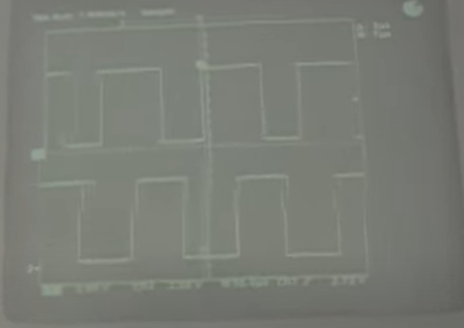
- The servo loop is the main control for the servo, its constantly asking the position, estimating the velocity and sending the control output. You want to measure the accurate timing between position estimation as this determines velocity estimates. If you use a PWM from the DAC card into the counter and you can measure between them, then you can estimate the timing precisely. This timing estimate can be used for the servo loop, so even if windows scheduler is not accurate you can measure the deviation and correct for it.
- Even if you gave the control loop signal at 1Khz its not really running at a 1Khz. The only way to confirm it is, in your code, when you enter the servo loop, toggle a digital out pin and use an oscilloscope to measure the frequency of the DO pin.
- Always be mindful of the enable lines, these go directly to your motor amps, not to the Daq cards, because if your computer freezes it will not work.
- For any kind of robots, its best to have a counter balance and back drivable so that if the power goes out the robot does not crash into the floor and you can move it out safely.
-
Linkages
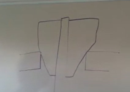
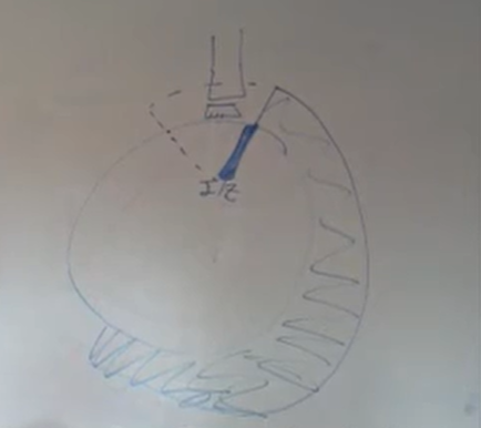
- Double parallelogram Remote center of Motion (RCM)
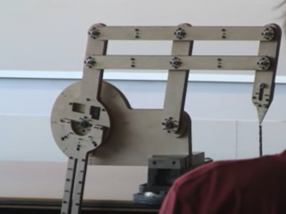
- There are mechanically enforced and Virtual Center of motion.
- The problems with some designs is that they are bulky, especially in medical robotics.
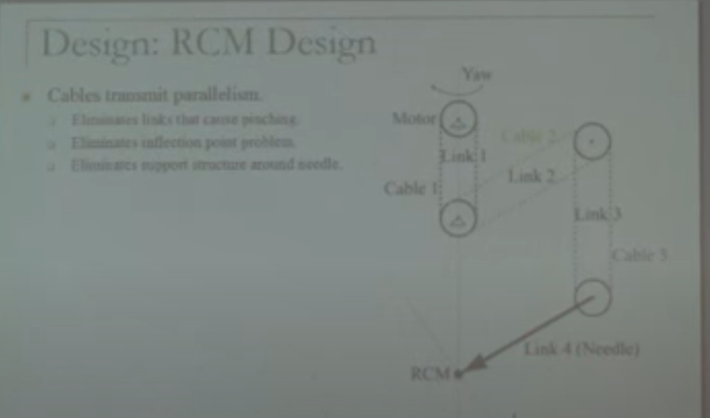
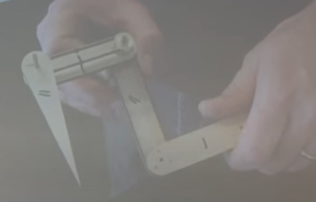
- The cables/belts enforce the prallelogram. The first pulley attaches to the first link and onto the pulley attached to the 3rd link. The metal pulley sits on a shaft that is attached to the 2nd link and a belt connects it to the last link.
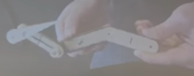
- They can move greater than the inflection point which would not be possible with a rigid link.
- These have higher range of motion and can give larger work area.
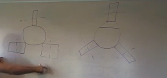
- Spherical joints

- They are called Rod Ends, Spherical joints, Swivels, Ball joints.
- They have a finite amount of rotation, one way to increase them is to make the ball bigger. Some ball joints/heads are ‘lined’ they have a bit of plastic between the two surfaces that helps to hold the position and with little bit of force change the rotation. common in tripod heads.
- This is a singularity as there is one of two ways the bar can rotate once they are in alignment, it could be parallel or phase shifted.
- In trains, to solve this problem they put the linkages on both sides of the axel with a phase shift of 90 deg. This is called Quater-locking
-
Counter Balance
- Counterbalance a robot arm with spring Youtube
- Why you want to counterbalance, first is that if the power goes off you don’t want your robot to come crashing down. You can use a break but if in the case of a medical robot, then you also want the ability to move the robot away from the patient when the power is off. Also if the robot is counterbalanced then you don’t need a bigger motor as its not trying to fight gravity. This limits the max force the motor can give and in case of an unexpected event limit the damage to person if its moving the wrong way.
- There are two ways to counterbalance your robot, mass and spring.
- When working with gravity use a spirit level to make sure the table is level so that your robot is aligned with gravity before debugging the counter balance.
- Mass based solutions are nice as it will work for any configuration your robot is in, even if you flip the robot sideways. Think of the camera crane.
- Springs need accurate gravity alignment to work properly. And you can’t turn them sideways then gravity would not pull down and the springs will still exert the same force.
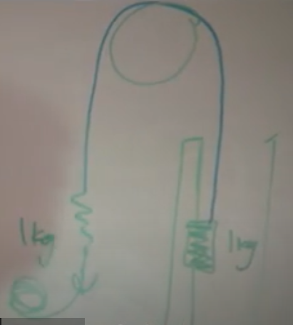
- The reason you might want to use springs is if you want rapid motion and adding mass is restrictive.
- You want to keep the robot light weight, so the lever arm of counter balance should be as long as possible. The counter balance should be as dense as possible to keep volume small.
- Steel is 7.37g/cc **is a great choice, but if you need something compact, go for **Tungsten which is 19.3g/cc **which is 3 times as dense as steel. Tungsten is cheap but it is difficult to machine. To make is easier to machine there is an alloy version of this called **18.5 Tungsten Tungsten.com is where you can get it machined.
- Make simple geometries with loose tolerances, you can’t tap tungsten. You can end mill it or Wire EDM.
- A two-part counterbalance. A steel backing plate with a tungsten counterbalance, the tungsten is on a slot so you can fine-tune the position. In a robot, you never want to take off the whole mass as it might collapse. There is always a fixed mass and a mass you can adjust to tune it.
- Another way to use tungsten is to use them as small pellets called Tungsten shots Tungsten balls.com They have no particulate matter only the spheres and are replacing lead as counterweights. The problem is that for spheres, the packing factor is only 60% but still greater than lead.
- The farther the counterbalance the larger the inertia. How can we have a low inertia counter balance? We can use a spring.
- To get accurate counterbalances, get your part from Mcmaster, measure the dimensions, weight it and get the actual density. Use it to update your cad and send the part to be machined.
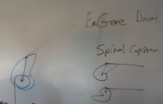
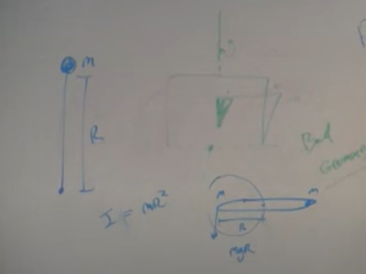
- Using a linear spring to get a non linear counterbalance force. Take a spring and attach it to a compound pulley with a spiral capstan attached. As the center distance is changing the force is also changing. If you do the math right, you can get any kind of non linear force displacement from the shape of the spiral capstan.
-
Measuring Instruments
-
Calipers
- The thing with precision instruments is that if your measurements are off, you want them to be off by large amount rather than a small amount so that you can intuitively look at it and know when it is happening. When using the inside jaws of your caliper the measurements will be off so that none of the fits will work but not enough to intuitively see if its happening.
- Calipers need to be in a box, if dust gets into it then its not precise anymore. They are good for about 0.0254 mm measurement.
- They have an inside jaw and an outside jaw. The outside jaw has flats ground on them and that is where they are most precise. The inside jaws are chamfered thin, as when you are measuring the internal diameter you only want two points of contact.
- Calipers are not best when measuring cylindrical objects, use micrometers instead. **Wiggle **the calipers to make sure you are measuring the min distance.
- Apply even but light pressure, or the material will compress and give wrong reading, like in delrin.
-
Micrometer
- They are the gold standard for outside measurement. They are good for about 0.001mm, 1 Micron measurement.
- Usually, the specification for tolerance of 8mm shaft is +0.000mm to -0.009 for the first one you will need to sand them to get them to fit. This is only possible to measure with a micrometer.
- Depth micrometer, are great because they have large flat face that you can rest on the part. They have stems that are longer than the instrument which allows you to measure a wide range of holes.
-
Pin gauges

- Pin gauges come in increments of 0.02mm and they are expensive.
- you can easily use them to find the fit you want for a shaft on a bearing or hole. The difference between a sliding fit and a press it is 0.001mm in metal.
- You can use pin gauges to align precise components like the linear rails which need accurate depth dowel pins.
- Way to install dowel pins will accurate height, you take two pin gauges with correct diameter, put the plate over it and press the dowel pins with a parallel plate.
- Measuring soft parts
- If your parts are softer than Delrin, don’t use calipers or micrometers.
-
Optical comparator
- An optical comparator is a precise camera you can use to measure squishy stuff. Dino light is a great example of digital microscope with measurement capabilites.
- Every time you change magnification you have to recalibrate.
- For holding parts which are not flat, you can use silicone ear plugs
-
Force sensor
- ATI Force sensor
- FSR force sensitive resistor FSR give voltage with respect to load applied. You need calibrate the FSR with known weights and get data points for various load and plot the curve. These can be done with calibration weights. FSR are good as long as you don’t apply tension or shear them.
- You can also use Calibration weights to find the stiction in your haptic device, you slowly add weights until it starts moving and you get the force required to start the motion.
- 123 or 246 blocks are good for measuring perpendicularity as well as setting perpendicularity. The holes are for helping mount the block so that it doesn’t fall off.
-
Calipers
-
Servo Motor
- Dynamixel Ax-12, the Mx series can do current based torque control. They are expensive as some of them have maxon motor in them.
- They are half duplex TTL UART.
-
Robot Frames and Tables
-
Aluminum Extrusion
- The cross-section of extrusion from 8020 are angled so that when you tighten them you deflect the beams, and it acts as a lock washer. When you order from Misumi, you get one on the right. If you don’t put a lock washer on them they will vibrate free. There are 2 extra parts per screw this is a pain when assembling.
- You can use the inside of the 8020 as pressure cylinders and tap holes in them to drive air.
- You want your base to be stiff and heavy as needed as if its not stiff then it will interfere with the servo control loop and if its not heavy enough to withstand the acceleration of the robot then it will shift.
- The top of the frame can be an Optical table top. They are flat stiff and heavy with spaced tapped holes for mounting.
- At some point you want to move your robot then you have to design in hooks and strapping points into it. If its heavy use an Engine crane to move the mass.
- Measure doors elevators, all access points you would need to cross. Always put a carper over the pallet jack before moving it as it will dampen out the vibrations.
- You can make a proto optical table with MDF and standard bolt pattern, use Tee nut to screw parts into the MDF.
-
Linear Stages
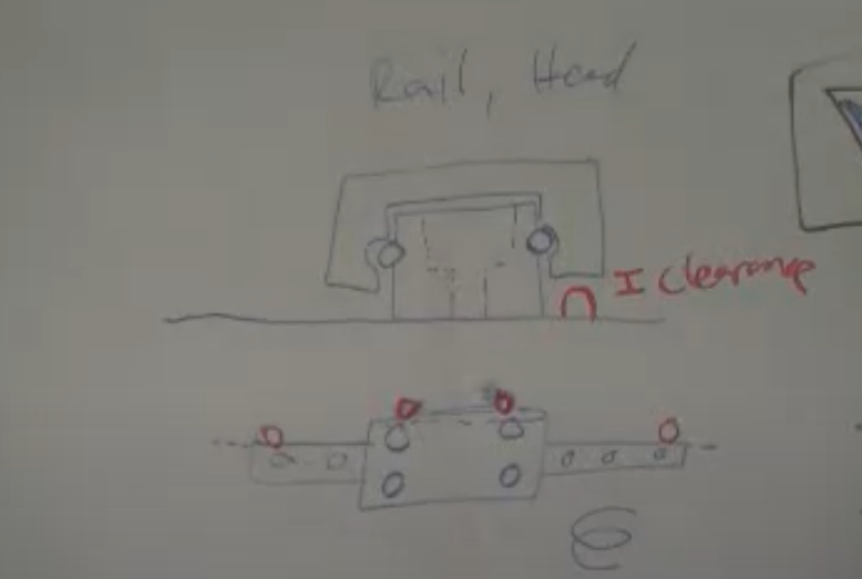
- Linear guideways have one side with notches on them that are perfectly parallel which allows you to locate the guide to the machine. Put dowel pins on the sides with the notches to get the guide aligned.
- Misumi gives a lot more info on their linear guideways. And they are almost always pre-loaded (light).
- What kills them are not forces, but torques, they have ratings on the maximum torque they can handle without ripping off. A way to increase torque capacity is to increase the number of slides in the linear rail, and if you want to increase torque capacity for the cantilever, you will need to add a second rail.
- SELBNL misumi, miniature linear slides with dowel holes.
- Misumi miniature linear slides
-
Powering Linear motions
- Rack and pinions are simple and they do not load the shafts of the motors very much, unlike belts and cables that have a lot of tension in them.
- Power Screws
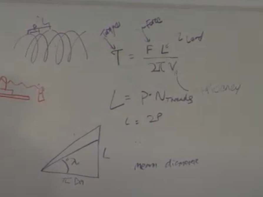
- For a given diameter of screws, if you want more efficiency (backdrivable) then you need to increased the number of threads in the screws, thereby increasing the lead L.
- Screws don’t have great accuracy, you need to look for lead accuracy to make sure that the distance travelled is the same in every rotation.
-
Aluminum Extrusion
- tags Applied Robotic Stanford CS235
Notes mentioning this note
Applied Robotic Stanford CS235
tags: Robotics #Making Prototypes Source CS235 Youtube What makes a good robot designer is the attention to the details. Every...
Archive
When a Note reaches a significant size they are indexed into the Archive. This is the only place where a...
Courses
Robotics Applied Robotic Stanford CS235 Fundamentals of Design Languages German Fabrication Making Prototypes Programming/coding AVR C Edx Single variable calculus...