Stepper Motor
- Tags: CNC Motors #Servo Stepper
- Resources
- Going twice as fast with stepper motor 101
- Gecko Stepper Basics
- Stepper basics Oriental motors
- Electromate various stepper motors
- Stepper tuning
- stepper motor basics nanotech Youtube
- Working principle of varioius stepper motors Homofasicines Youtube
- Stepper accel derivations
- Generate stepper motor accel in real time
- Pytron Stepper motor dampers
- AMS Stepper motor control basics
- Stepper motor specs basics detailed
-
Stepper motor for High Speed
- Time constant for stepper motor is given by ratio L/R and is the time to reach 63% of charge or discharge. Higher voltages help push more current faster but will lose a lot of power due to eddy currents as heating is not depended on load but on the PWM frequency and duty cycle.
- Transient inductance Calculate time constant for iductors.
- Stepper drives
- Driver IC #IC Chips
- DRV8428 35V 1 A integrated current sensing
- TMC
- Klipper TMC tuning docs
- TMC stepper drivers changing the driver_PWM_GRAD from the default of 4 to instead something like 10 has the biggest improvement on performance. the factory default from TMC is set really low because they don’t know what kind of capacitance will be available but if you mainboard has decent sized caps used then you can set it to 10 with no issues. maxing the PWM_GRAD had a bigger improvement on performance than 48V or using bigger stepper motors because with something like a core-xy printer the real bottleneck is how aggressively the stepper driver ramps up the current while accelerating.
- Sourcing
- Important parameters
- Rotor inductance in henrys/coil resistance in ohms to measure time constant in sec.
- Impedence match load interia to rotor inertia should be from 1:1 to 10:1, closer to 3:1 give higher performance.
- Bias motor to run at max power setting just past corner frequency.
- Increasing current increases torque till magnetic saturation. rated current is sufficent.
- Load stepper between 30-70% of the rated torque and test. Add inertial mass if need more damping.
- Usual resonant frequency is 200hz try to stay above the resonant region.
-
Choosing a stepper motor
- Ideally, the motor should deliver sufficient at the highest speed the application requires and no more. Any torque capability in excess of what the application requires comes at the high cost of unnecessary motor heating. Excess torque capability beyond a reasonable safety margin will never be used but will exact the penalty of an oversized power supply, drive stress, and motor temperature.
- high initial torque at low speed does not mean efficient motor utilization. Usually, power is the more important measure of a motor’s suitability to an application. To determine this, you must bias the motor’s operating point through power transmission gearing to operate the motor at its maximum power; normally just past its corner frequency.
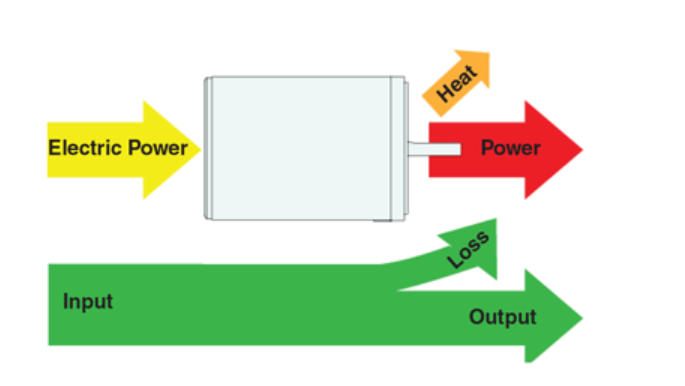
- An efficient motor, defined** as the smallest motor sufficient to meet the demands of the application, will run hot.** Think of the motor as having fixed power conversion efficiency: Some percentage of the input power will be converted to heat and the rest will be converted to mechanical power. To get the maximum performance from the motor, the waste heat must be just under what the motor can tolerate. Usually, this motor will be biased to operate just past the corner speed as well.
- Power levels for IC-driven stepper motors typically range from below a watt for very small motors up to** 10 – 20 watts for larger motors. The **maximum power dissipation level or thermal limits of the motor are seldom clearly stated in the motor manufacturers’ data. To** determine this we must apply the relationship P␣ =V ×␣ I.** For example, a size 23 step motor may be rated at 6V and 1A per phase. Therefore, with two phases energized the motor has a rated power dissipation of 12 watts.
- It is normal practice to rate a stepper motor at the power dissipation level where the motor case rises 65°C above the ambient in still air. Therefore, if the motor can be mounted to a heatsink it is often possible to increase the allowable power dissipation level. This is important as the motor is designed to be and should be used at its maximum power dissipation,to be efficient from a size/output power/cost point of view
- To start is to determine the load torque in oz/in, including the torque necessary to accelerate the load. The next step is to come up with the maximum speed the application has to operate at in full steps per second
- RPS * 200 = PPS
- Multiply the PPS value by the number of oz/in determined previously and divide the total by 4506. The answer will be how many watts mechanical are required from the motor to meet the load from the application. When picking a motor, choose one with 40% more than the calculated power. Below is an example of the equation completed for a load requiring 450 oz/in with a 3 TPI leadscrew and the desired IPM of 300.
- **(300 * 3) / 60 = 15
15 * 200 = 3000
(3000 * 450) / 4506 = 299 OZ/IN
299 * 1.4 = 419 OZ/IN** - As you can see, you will want to use a motor with a rating of 419 oz/in for this application.
-
Motor temperature calcs
- Why stepper motors get hot
- Nema Mg1 standard
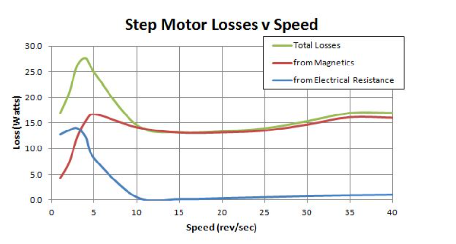
- Step motors waste power in two ways:** copper losses** that result from the electrical resistance of the stator coils and** iron losses from magnetic hysteresis** and eddy currents.
- Copper losses are highest at lower speeds where the motor back emf and inductance do not prevent the driver from applying full current to the stator coils. Magnetic losses from hysteresis, on the other hand, increase uniformly with speed. Eddy current losses are the product of current and frequency, so they tend to create a big** spike at 5 – 10 rev/sec** and then taper off.
- Typical losses for a Nema 23 operatnig at 24V.
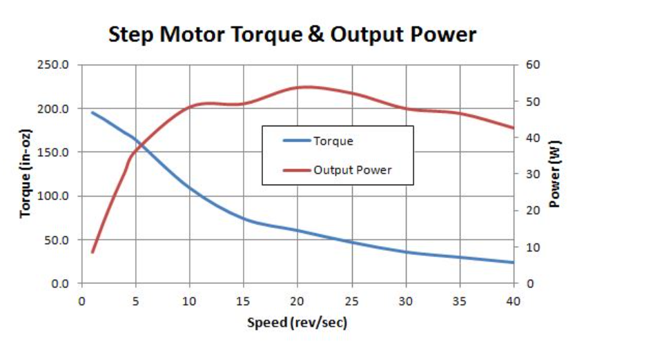
- how a step motor’s torque drops off as speed increases. Because output power is the product of speed and torque, it actually increases with speed, reaching a peak of 54 watts at 20 rev/sec.
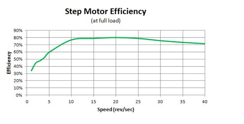
- By comparing input power to output power we can determine step motor efficiency at any given speed. At full load, step motors can achieve efficiency as high as 80%.
- Rated motor power can be found from the P = V x I given on motor specs.
- Heat generated is Q = I^2 x R x t(secs)
- The average hybrid motor is about 65% efficient,
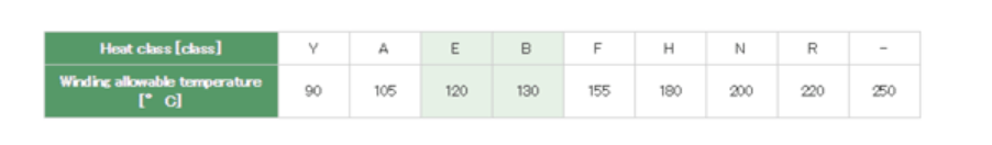
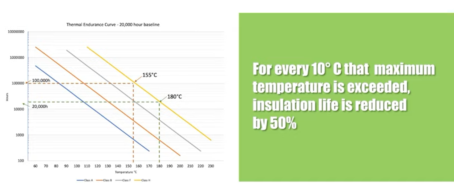
- Nema Mg1 establishes 4 standards of heat the insulation system can witstand for a specifed temperature giving a specific operating time.
- Nema class defines the max temperature of the winding with an allowable margin that would give a life of 20,000 hrs.
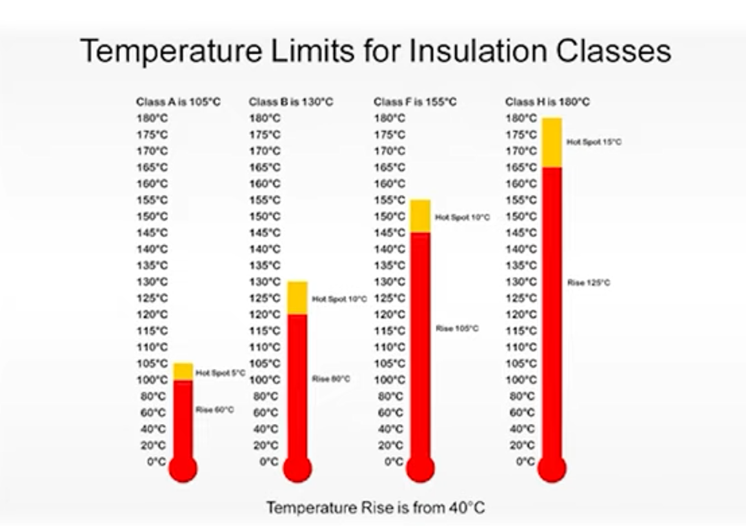
- As the winding temperature inside the motor can not be measured directly, measure the surface temperature of the motor case as a reference.
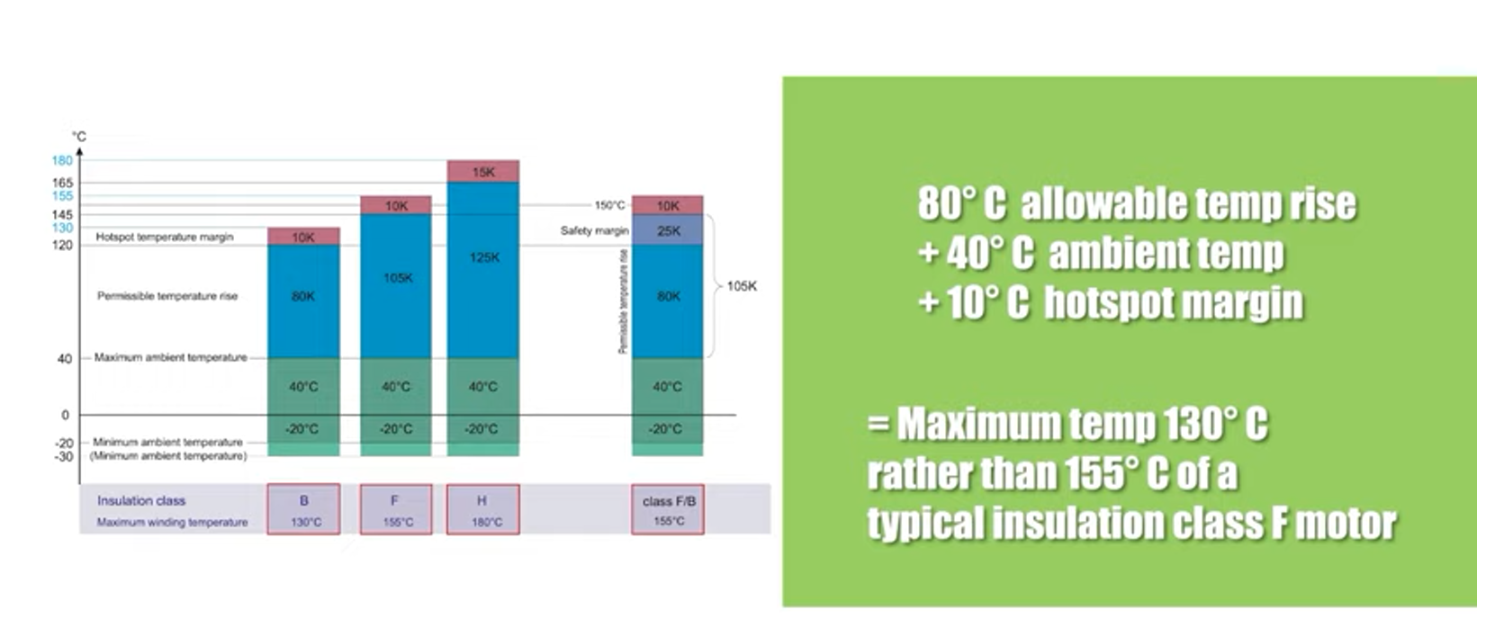
- The Class B rating is 130°C (266°F). There is an approximately 30°C (86°F) temperature drop form the windings themselves to the motor case surface. Therefore, the maximum case temperature should be 100°c (212°F).
- To determine the maximum ambient temperature of our stepping motors, we know that the maximum temperature rise for a stepping motor at rated voltage and two phases ON is 80°C (176°F) from experimentation. If you subtract the maximum temperature rise of the motor 80°C (144°F) from the maximum winding termperature of 130°C (266°F), the maximum ambient temperature for a stepping motor would be 130°C - 80°C = 50°C (122°F)
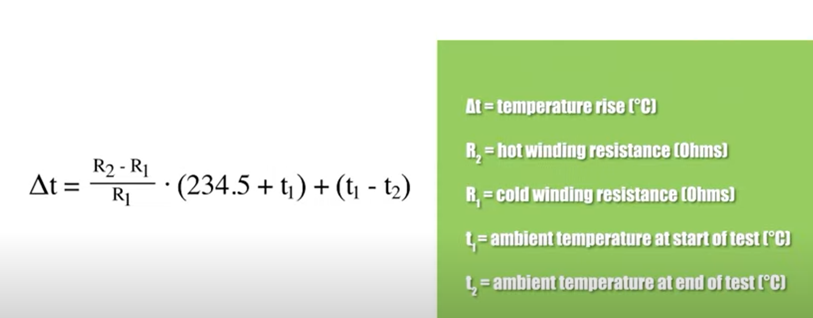
- Temperature rise is foundby measuring the differrence in resistance when motor is run at full load.
-
5 phase stepper motors
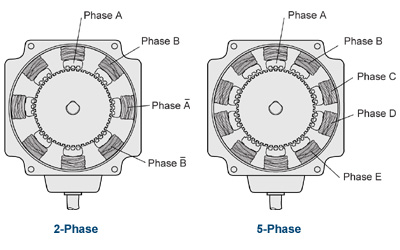
- The most obvious difference between 2-phase and 5-phase (see interactive diagram below) is the number of stator poles. While 2-phase motors have 8 poles, 4 per phase, the 5-phase motor has 10 poles, 2 per phase. The rotor is the same as that of a 2-phase motor.
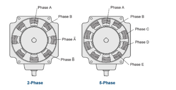
- While the 2-phase motor moves 1/4 tooth pitch each phase. The 5-phase, because of its construction, moves 1/10 of a tooth pitch. Since the pitch is still 7.2°, the step angle is 0.72°. Simply based on construction, the resolution of the 5-phase has 500 steps per revolution versus the 2-phase with 200 steps per revolution. The 5-phase offers a resolution 2.5 times better than that of the 2-phase.
- In both 2-phase and 5-phase, the rotor must overshoot or undershoot more than 3.6° to miss steps. Because the step angle of the 5-phase is only 0.72°, it is almost impossible for the motor to overshoot or undershoot by 3.6°. The chances of losing synchronism with a 5-phase stepper motor are very low.
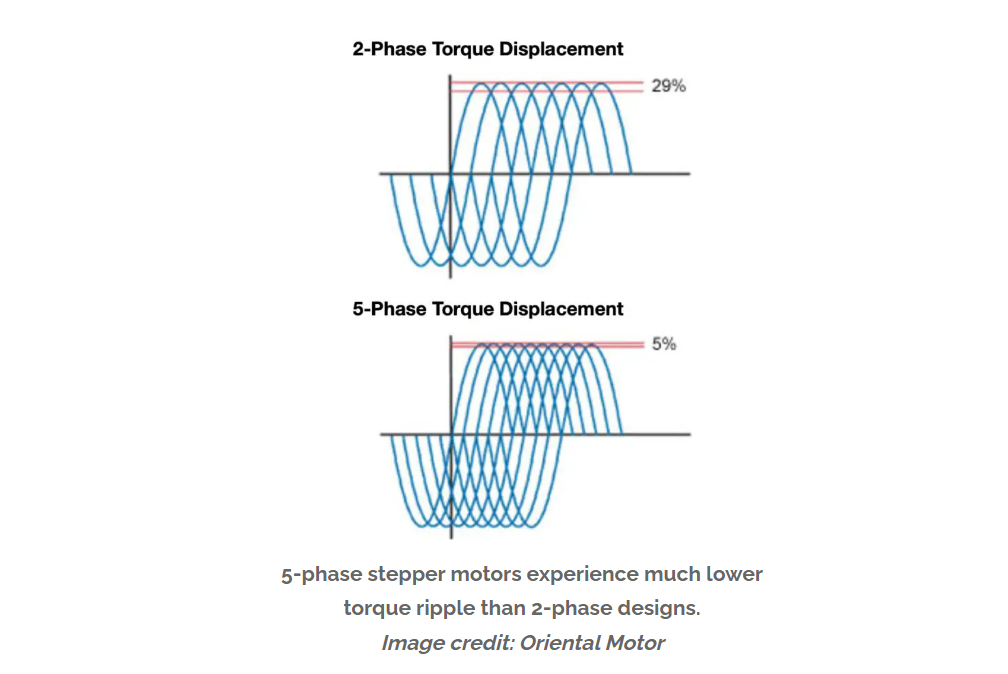
- Five-phase stepper motors also have less torque ripple, and in turn, more usable torque than other designs. The torque produced by each phase contributes to the total output torque of the motor. As each phase is energized and the rotor moves, a sinusoidal torque-versus-displacement curve is produced
-
Construction
-
2 Phase motor vs 5 Phase motor Oriental motors
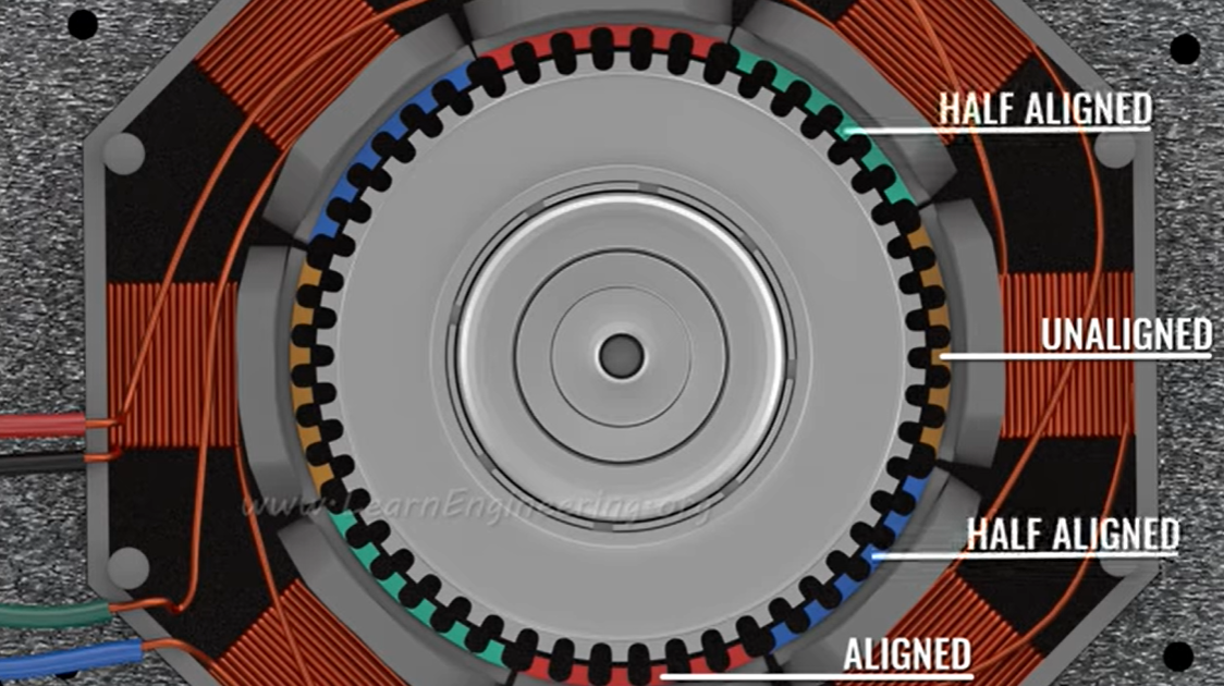
- Hybrid stepper motors have an axially magnetized rotor and 50 teeth. It utilizes both the reluctance and the magnets to move. The shaft side is the south pole of the rotor. The teeth on the north pole and south pole are shifted by one half tooth width.

- The stator has 2 few teeth and they are arranged into 4 coil pairs red, blue, green, and yellow. The way they are arranged is that one pair of teeth is aligned to the teeth on the stator and the other is unaligned. The remaining coils are only half-aligned.
-
2 Phase motor vs 5 Phase motor Oriental motors
-
Commutation
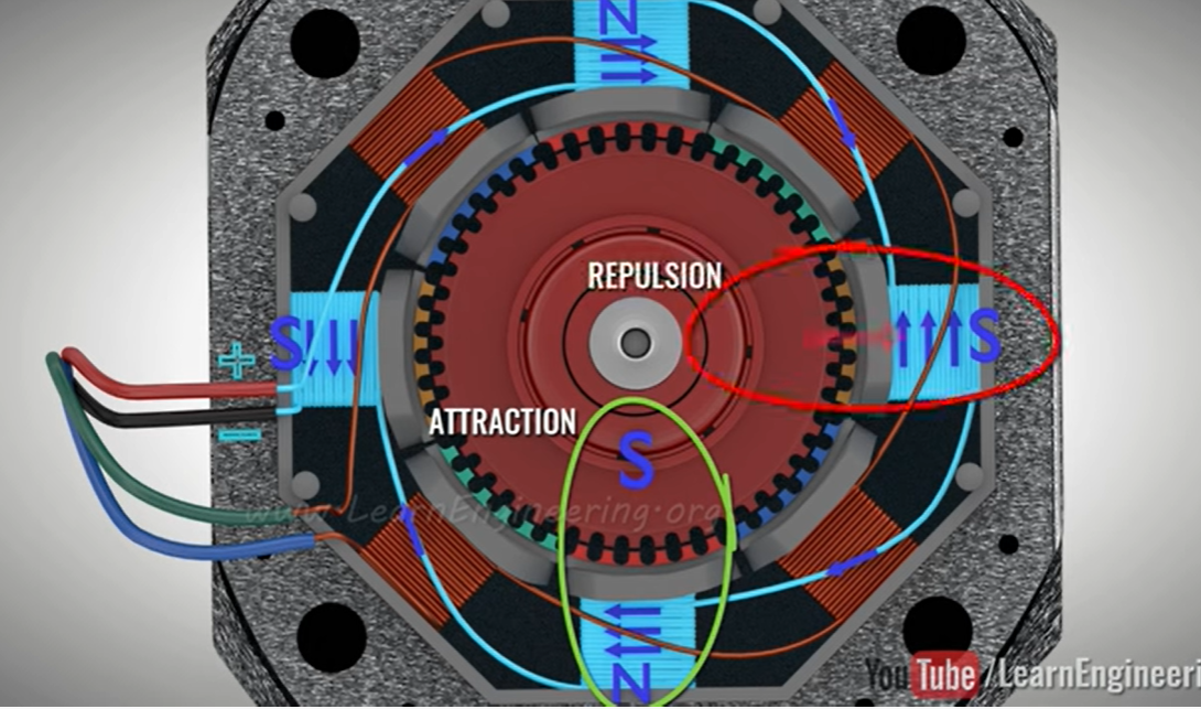
- In the first step, considering the shaft side south pole, when the first coil pair is energized the rotor aligns itself with the North pole, and the south pole attracts the North pole of the rotor which have teeth shifted by one tooth from the south pole of the rotor.
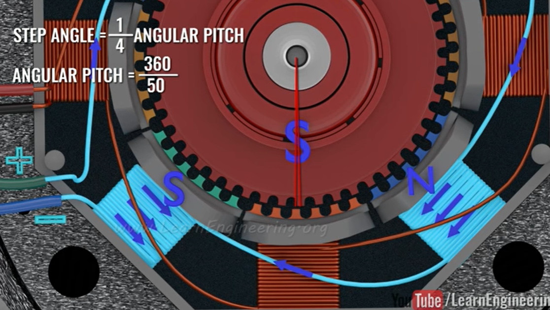
- When the coil B is energized the rotor has to move by a small angle equal to 1/4th the angular pitch which is 1.8 deg.
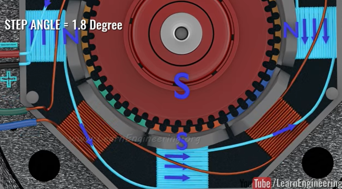
- Now the First coil is energized with the opposite polarity, and the rotor has to move by a small amount to align with the stator.
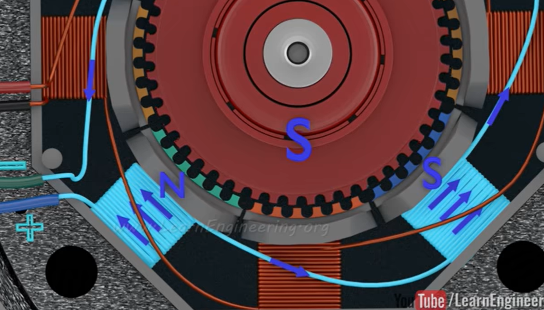
- The last step is to energize the second coil with the opposite polarity.
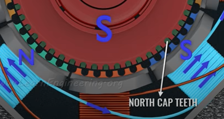
- The North end cap teeth are placed in between the south end cap teeth, this ensures that the opposite poles are in alignment with the stator.
-
Characteristics
- Geko speed torque
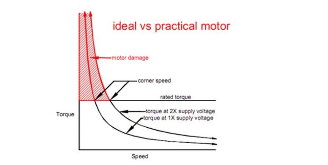
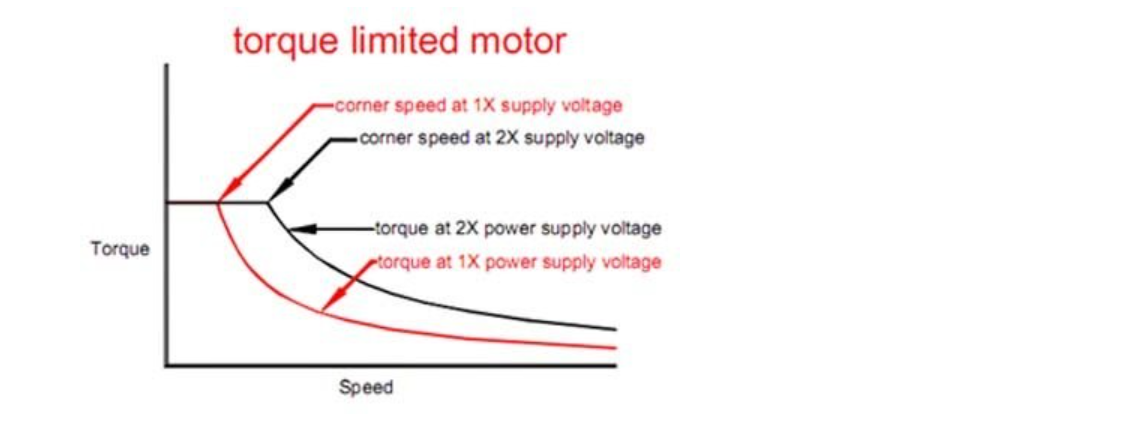
- Below a certain speed, called the** corner speed**, the current would rise above the motor’s rated current, ultimately to destructive levels as the motor’s speed is reduced further. To prevent this, the drive must be set to limit the motor current to its rated value. Because torque is proportional to current, motor torque is constant from zero speed to the corner speed. Above the corner speed, motor current is limited by the motor’s inductive reactance.
- A real stepper motor has losses that modify the ideal speed-torque curve. The most important effect is the contribution of detent torque. Detent torque is usually specified in the motor datasheet. It is always a loss when the motor is turning and the power consumed to overcome it is proportional to speed.
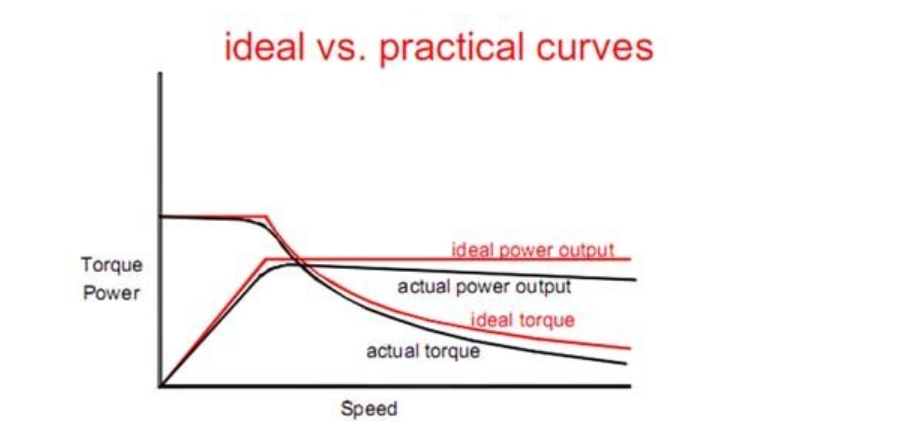
- the power output decreases with speed because of the constant-torque loss due to detent torque and other losses.
- Finally, there is a rounding of the torque curve at the corner speed because the drive gradually transitions from being a current source to being a voltage source.
- Oriental motors
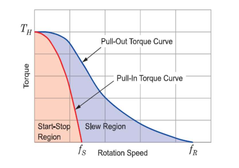
- In order to operate in the region between the pull-in and pullout, the motor must first start in the start/stop region. The pulse rate is then increased until the desired speed is reached. To stop, the motor speed is then reduced until it is below the pull-in torque curve.
- Torque is proportional to the current and the number of turns of wire. If we want to increase the torque by 20%, we should increase the current by about 20%.
- Because of** magnetic saturation**, there is no advantage to increasing the current to more than 2 times rated current. At that point the increase in current won’t increase the torque. At about 10 times rated current you run the risk of demagnetizing the rotor.
- Inductance **affects high speed torque. Each motor winding has a certain value of inductance and resistance. Inductance in henrys, divided by the resistance in ohms, gives us a value of seconds**. **This amount of seconds (time constant) is the amount of time it takes the coil to charge up to 63% of its rated value. **If the motor is rated for 1 amp, after 1 time constant, the coil will be at 0.63 amps. After about 4 or 5-time constants the coil will be up to 1 amps. Since torque is proportional to current, if the current is only charged up to 63%, the motor will only have about 63% of its torque after 1 time constant.
- The higher the ratio of drive voltage to motor voltage, the better the high speed performance. High voltages force the current into the windings at a faster rate than the 63% mentioned above.
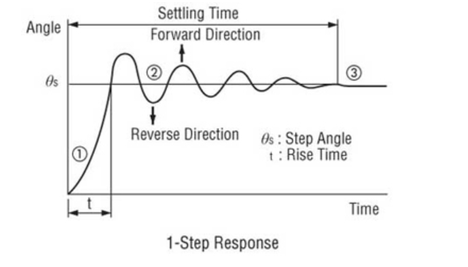
- Unloaded, the motor exhibits a lot of ringing. A lot of ringing means a lot of vibration. The motor will often stall if it is unloaded or lightly loaded because the vibration is so high it will lose synchronism. When testing a stepper motor always be sure to add a load.
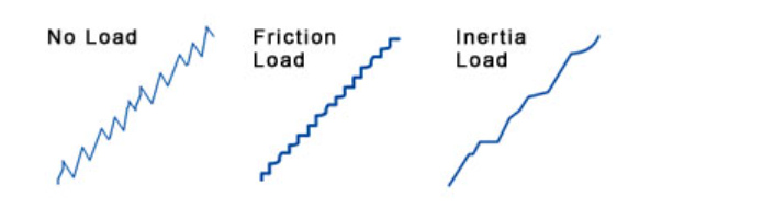
- Loading a motor properly will smooth out its performance. The load should require between 30% to 70% of the torque the motor can produce, and the ratio of load inertia to rotor inertia should be between 1:1 and 10:1. For shorter, quicker moves, the ratio should be closer to 1:1 to 3:1.
- The motor will exhibit much wilder vibrations when the** input pulse frequency matches the natural frequency of the motor. This is called resonance and usually occurs around **200Hz. In resonance, the overshooting and undershooting become much greater and the chance of missing steps is much higher. The resonance changes depending on the load inertia, but it is usually around 200Hz.
- 2-Phase stepper motors can only miss steps in groups of four. If you are missing steps in multiples of four, the vibration is causing a loss of synchronism, or the load is too great. If the missed steps are not a multiple of four, there’s a good chance the wrong number of pulses or electrical noise is causing the problems.
- There are a number of ways to get around resonance. The easiest way is to avoid that speed altogether. 200 Hz is not tremendously fast, for a 2-phase motor that is 60 rpm. Most motors have a maximum starting speed around 1000 pps or so. So in most cases you can start the motor at a higher speed than the resonant speed.
-
Another solution is to make the step angle smaller. The motor will always overshoot and undershoot more for bigger step angles. If the motor doesn’t have to travel far, it will not build up enough force (torque) to overshoot a large amount. Anytime the step angle is made smaller, the motor will not vibrate as much. This is why half-stepping and microstepping systems are so effective at reducing vibration.
-
Pullout Torque (Slew rate)
- It is the maximum torque that a stepper can generate at a given speed without missing steps. Found by accelerating the motor to a target speed and increased the torque on the shaft until the motor slips, performed over a range of speeds to get a curve.
- This is a plot of the pullout curve for a common stepper motor. The light-blue line contains the area of slew rate or pullout curve. The dark blue line plots the pull-in curve or start/stop region, which shows the maximum frequency at which a loaded stepper can stop and start without losing steps. The red line is mechanical power output. These plots change if there’s inertial mismatch.
- A related value is stepper motor pull-in curve — the maximum frequency at which a loaded stepper can start and stop without losing steps.)
-
Inertial mismatch #Drive Transmission #Impedance matching
- An ideal way to use a stepper motor is to match the inertia of the motor to that of the load but often not practical for higher performance, load : motor could be 3:1 but best to keep it under 10:1. Proper sizing of motor helps match inertia, else running the motor through long acceleration/deceleration cycles also helps but with less efficiency.
-
Tuning Stepper motors
- TI tuning steppers
- Tuning means, how well the current regulation scheme maintains the current in a stepper motor’s coils. A poorly tuned stepper motor will have a jerky motion and significant vibration.
- Tuning the stepper motor can be time-consuming because finding the optimal fixed decay settings for a given motor, voltage, current and speed is a trial-and-error process.
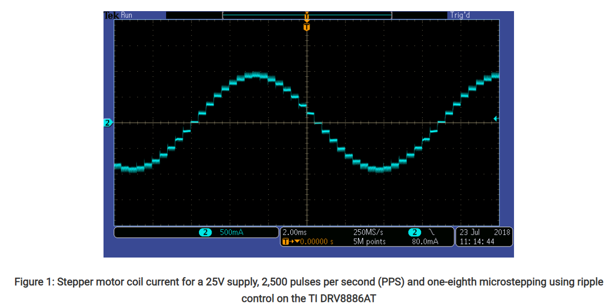
- A tuned waveform looks like the above.
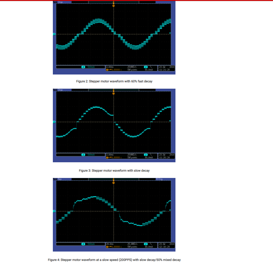
- decay setting chosen for the above current regulation scheme (also called current chopping) was not appropriate for the chosen motor, supply voltage, full-scale current, and speed.
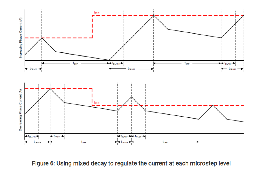
- Stepper **motor tuning is the process of choosing the proper decay setting **during the off time of the PWM current chopping cycle (tOFF).
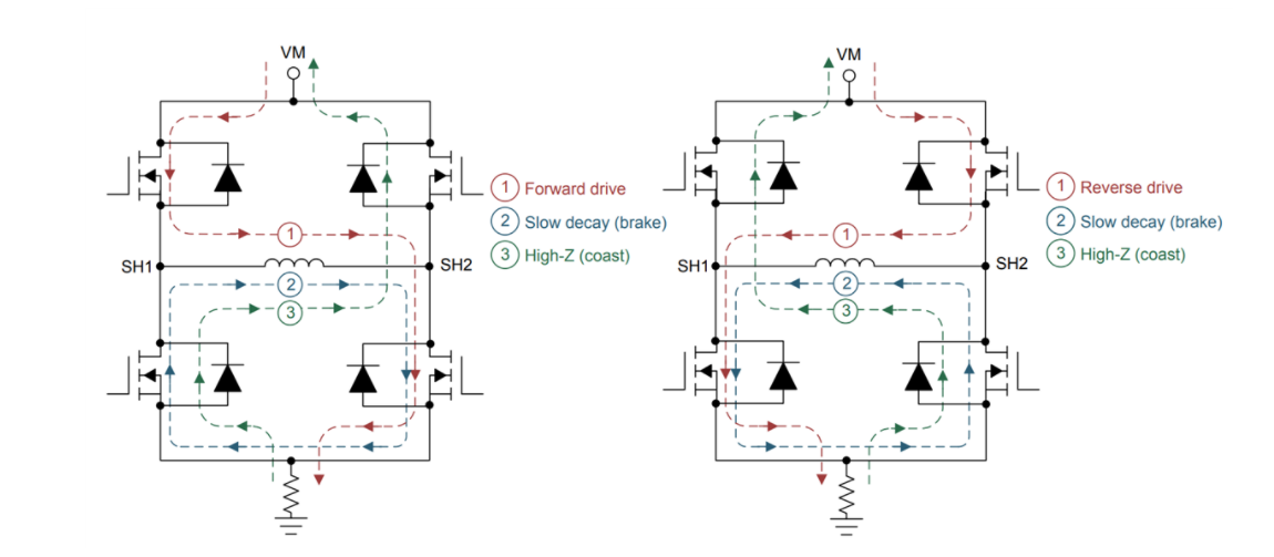
- During fast decay, the field-effect transistors (FETs) opposite from the driving FETs turn on, and the current flows from the motor back to the power supply. For this condition, the current decreases quickly. During slow decay, the two low-side FETs turn on, and the current recirculates through these FETs. For this condition, the current decays much more slowly.
- High step rate causes back EMF of the motor to be significant, and slow decay is not sufficient to regulate the current during the decreasing steps.
- During stepper motor tuning, engineers search for the optimal “mixed” decay setting for the stepper. Mixed decay consists of a combination of fast and slow decay when the driver is not driving current into the coils. Choosing the mixed-decay settings means setting the percentage of fast decay versus slow decay for the off time.
- Devices like the DRV8880, DRV8881 and DRV8886AT have smart tuning features that can help eliminate the time-consuming effort of stepper motor tuning.
- tags: CNC Motors #Stepper Motor
Notes mentioning this note
Applied Robotic Stanford CS235
tags: Robotics #Making Prototypes Source CS235 Youtube What makes a good robot designer is the attention to the details. Every...
Motors
tags: Brushless DC motors Robotics Actuators Resources Understanding motors Youtube Jatzen lee, Space vector commutation, Clark park transform, sinusoidal, FOC...
Servo Stepper
tags: CNC Motors #Stepper Motor Resources Low cost FOC control for Stepper motors FOC stepper FOC Hybrid Stepper motor Odrive...
Stepper Motor
Tags: CNC Motors #Servo Stepper Resources Going twice as fast with stepper motor 101 Gecko Stepper Basics Stepper basics Oriental...