Servo Stepper
- tags: CNC Motors #Stepper Motor
- Resources
- Opensource Projects
- Stmbl Servo stepper Rene Great hardware/software
- Misfittech nano stepper HW/FW docs on running
- servo stepper sam #Sam calish MIT
- mechaduino Firmware base for many projects learning
- Arduino Simple FOC Stepper control
- ustepper
- Position closed loop stepper
- MKS servo China board
- Bigtree tech stepper board
- Simple FOC library stepper motor
- Servostepper
- IC Chips
- Solutions
-
Closed loop stepper control
- **Step-loss compensation: **Reactive position correction at the end of the move. Uses encoder to check the position after a move is made and corrects for any deviation, not real-time.
- **Load position control: **Continuous, real-time position correction without complex controls. Stepper still operated in microstepping mode, encoder checks the position against the commanded move and continuously corrects for any errors.
- Servo control: Complete control of torque and position stepper operated as a 2 phase BLDC provides current control and allows to operate at full rated torque.
-
Servo control
- The method of converting ordinary stepper motors into Closed loop servo motors by adding an encoder and operating the motor as, effectively, a commutated two-phase Brushless DC motor.
- stepper servo can actually outperform brushless motors in areas such as acceleration rate and torque output. This makes it a candidate for applications such as high-speed point-to-point moves, textile equipment, coil winding, high-speed electronic cams, and more.
- step motors, the phasing techniques that the amplifiers employ are given special names such as full step, half step, and microstep control. These different techniques refer to the number of power levels that are applied to each motor coil during an electrical cycle.
- Stepper servo is different form closed loop control which just used an encoder to verify the position.
- The first requirement is that it requires a very high resolution encoder to be attached to the stepper motor about 2000 counts/rev.
- The second difference is that stepper servo operation runs the motor like a Brushless DC motor and commutates the phase angle using the actual encoder position rather than the commanded position.
- The third difference is that rather than being constant, the height and phase angle of the waveform are continuously varied based on the output of a position PID loop, which is used to servo on the commanded position.
- These traditional controllers often use relatively simple current control techniques such as fixed off-time PWM (Pulse Width Modulation) and do not explicitly command the current during all phases of the motor’s electrical cycle. In particular, to decrease the current in the coil an uncontrolled decay mode (sometimes selectable as fast decay or slow decay) is used.
- While good-enough for most traditional step motor controllers, this will not work well for stepper servo controllers. Stepper servo controllers instead borrow the control schemes used with a Brushless DC motor, and explicitly control current through all phases of the generated waveform.
-
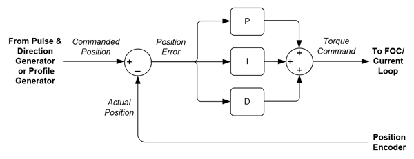 **
** - Current control can be accomplished in a few ways, but increasingly Field Oriented Control (FOC) is used even for step motors. While often associated with Brushless DC motor control, FOC has significant benefits when controlling step motors which include higher top speed and more efficient operation.
-
FOC control of Stepper motor
- Stepper behave like BLDC motors with high pole counts, which give them large torque and resolution at lower end but limited top speed. The control loop also has to run much faster to achieve higher speed.
- Steppers are rated for continuous current, since current requirements when FOC’ing is low they can be pushed to higher currents to deliver more torque.
- Tags: CNC Motors #Servo Stepper
Notes mentioning this note
Brushless motor Controller
tags: #Brushless DC motors Servo SimpleFOC FOC Resources Theory Space Vector Modulation FOC #Servo Control #Servo Stepper TI motor control...
Motors
tags: Brushless DC motors Robotics Actuators Resources Understanding motors Youtube Jatzen lee, Space vector commutation, Clark park transform, sinusoidal, FOC...
Servo Stepper
tags: CNC Motors #Stepper Motor Resources Low cost FOC control for Stepper motors FOC stepper FOC Hybrid Stepper motor Odrive...
Stepper Motor
Tags: CNC Motors #Servo Stepper Resources Going twice as fast with stepper motor 101 Gecko Stepper Basics Stepper basics Oriental...