Motors
- tags: Brushless DC motors Robotics Actuators
- Resources
- Understanding motors Youtube Jatzen lee, Space vector commutation, Clark park transform, sinusoidal, FOC basics.
- BMW i3 traction drive Youtube
- How real motors work John storey Explanation on different motor types.
- Things in Motion #Brushless DC motors Good info on brushless motors.
- Things in motion Recommended reading #Brushless DC motors Robotics
- Miniature motors for Medical devices
- Simple motor DIY buildable
- Motor terms part1
- Motor terms part2
- Increasing motor efficiency
- Motor control Compendium #Brushless motor Controller
- Electrical motor design resources
- Motor Servo with Backlash MIT
- Motor constants
- Faulhauber DC motor calculations Motor constants, speed curves, power, sizing
- Kollmorgen measuring torque constant
- Tools
- Technology
- Soft magnetic composites powdered magnetic powder for creating 3D laminations.
- Thingap coreless brushless motor
- Types
-
Construction
-
Salient vs non salient pole rotor
- Salient or projected pole rotors have discrete pole made of laminated steel. Larger in diameter and for slow speed applications. They have high pole counts as they operate at slow speeds. Flux distribution is relatively poor and generated waveform is not uniform. Need damper windings to prevent oscillations.
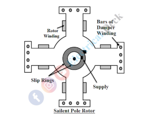
- Non salient or cylindrical pole rotors are made of solid steel and have parallel slots in them to accommodate the rotor windings. Smaller in diameter and longer axial length less peripheral velocity less windage loss, low noise, high speed nuclear, thermal power plant.

- Salient or projected pole rotors have discrete pole made of laminated steel. Larger in diameter and for slow speed applications. They have high pole counts as they operate at slow speeds. Flux distribution is relatively poor and generated waveform is not uniform. Need damper windings to prevent oscillations.
-
Salient vs non salient pole rotor
-
Understanding Electric motors
- Magnetic fields in a material are cause by the synchronized rotation of charged particles oriented in along the same direction.
- The forces on a charged particle are given by Lorentz equation which is given by
F= qE + qV X B
Where qE is force experienced because of the electric field and proportional to the charge and the strength of the field and will be in the same direction as the field.
qV X B **when the charged particle is moving through a magnetic field, the force is proportional to the charge and the component of velocity perpendicular to the magnetic field and the strength of the magnetic field. The force acts perpendicular to both the direction of the velocity and the magnetic field. - The current in a wire is the net charge flowing per time dq/dt, for a wire of length **L carrying a current i placed perpendicular to a magnetic field with strength B the force on the conductor is given by,
F= iL x B
Hence the torque on a current-carrying loop of wire is given by T = d x (iL x B), where d is the diameter.
These are all #Cross product as the resultant is always perpendicular to the inputs. - Faradays Law states that the magnetic flux in a loop cannot change suddenly, hence the motion of the conductor through the magnetic field induces an EMF in the wire, this is commonly known as the back emf. - If we assume that the current-carrying conductor is perpendicular to the magnetic field, then we can write F= iLB as cross product of perpendicular vectors is product of their magnitude. - Then torque T = d x F, = d x iLB => T= diLB Sin(θ+90) since these are vector components, and the force vector is 90 deg to the magnetic field. Sin(θ+90)= Cos(θ), Which gives us T= diLBCos(θ) As the cosine will give the perpendicular distance the force is acting on with respect to the position of the coil.
- 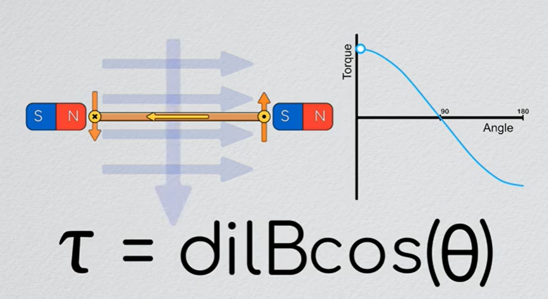 The torque generated by the coil is maximum when it is inline with the magnetic field, another way to say it is that the **torque is maximum when the magnetic field induced by the wire is perpendicular to the external magnetic field**
- When the coil is at 90 deg to the magnetic field, the net torque generated is zero. There is no current which we can send to it that will move it out of this orientation. Hence to prevent this condition, 3 coils offset by 120 deg are used, and it switched the currents through these coils in a process called **commutation**.
- 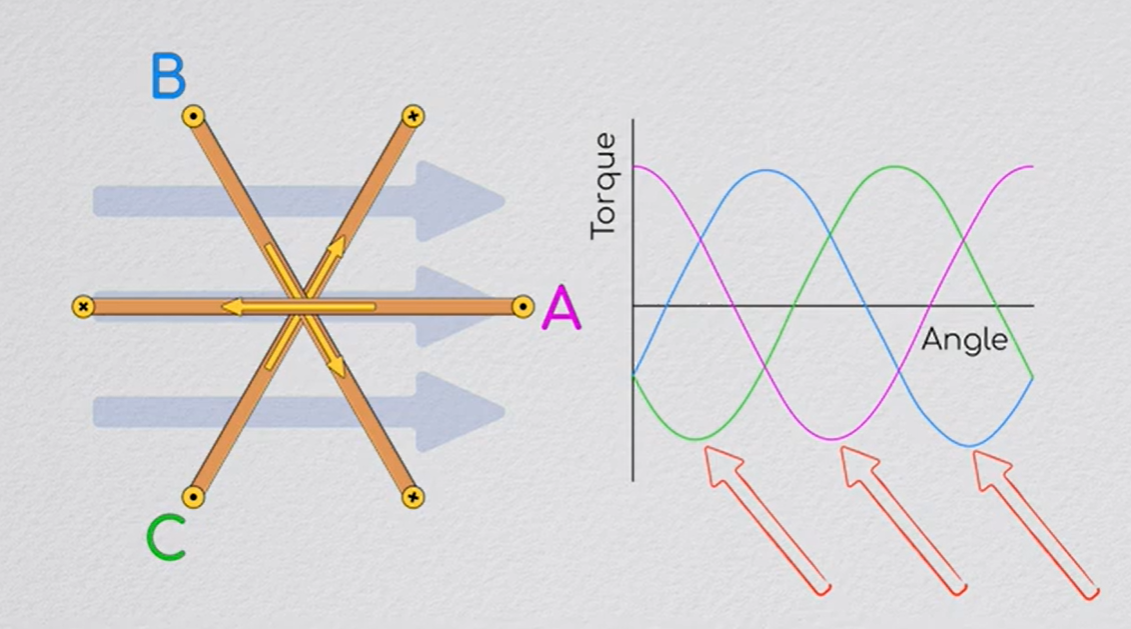
- If we run our current as in the directions shown we can generate positive torque in one part of the cycle, but we are losing out on the other half when our loops are aligned with the magnetic fields.
what if there was a way to connect the coils in such a manner than the positive current through one coil would flow in the opposite direction in one of the other two coils. If we timed these correctly then we can effectively reverse the direction of the negative torque.
 - There are two ways we can connect these coils,
-
- There are two ways we can connect these coils,
-  - In star connection, positive voltage applied to A sets up a current of V/2R on coil a and -V/2R on B when B is connected to ground.
-
- In star connection, positive voltage applied to A sets up a current of V/2R on coil a and -V/2R on B when B is connected to ground.
- 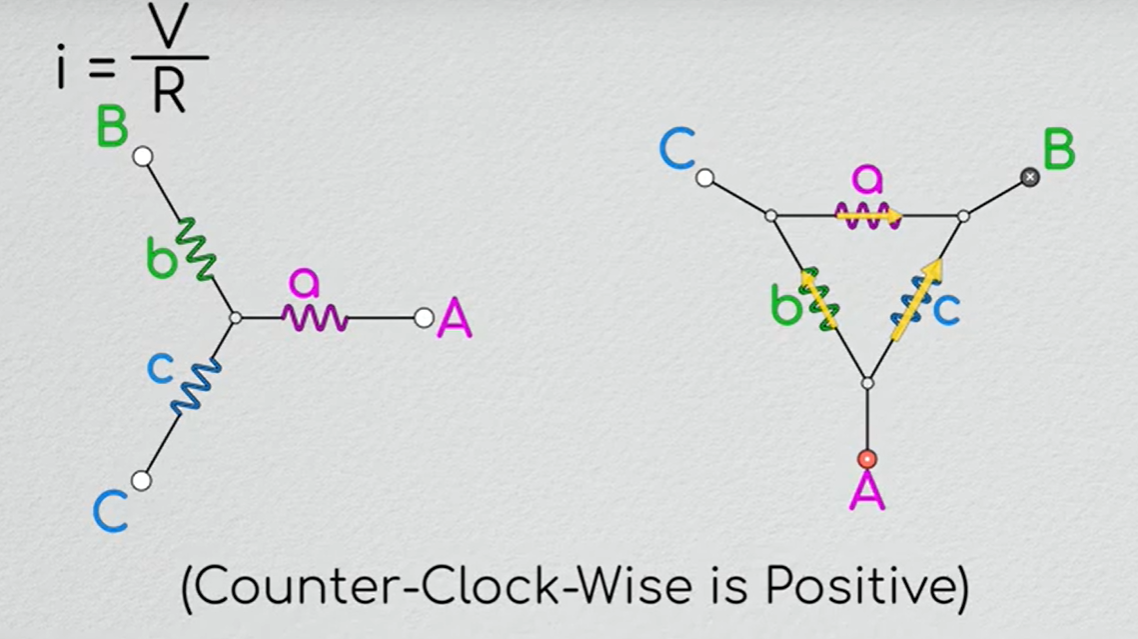 - In delta configuration, A positive voltage applied to A will set up a current of -V/2R in both coil b and a and a positive current of V/R in coil c.
- Both #Star and Delta connection have their advantages and disadvantages, but they commutate the same way.
- We want the coil with maximum positive torque connected to positive and the loop with the maximum negative torque connected to ground. Hence the current will flow positively in the positive torque loop and negatively in the negative torque loop.
- If we play through the rotation of the coil, then we can see that we only need to connect the coil to power when they are within 60 degs of the magnetic field vector.
-
- In delta configuration, A positive voltage applied to A will set up a current of -V/2R in both coil b and a and a positive current of V/R in coil c.
- Both #Star and Delta connection have their advantages and disadvantages, but they commutate the same way.
- We want the coil with maximum positive torque connected to positive and the loop with the maximum negative torque connected to ground. Hence the current will flow positively in the positive torque loop and negatively in the negative torque loop.
- If we play through the rotation of the coil, then we can see that we only need to connect the coil to power when they are within 60 degs of the magnetic field vector.
- 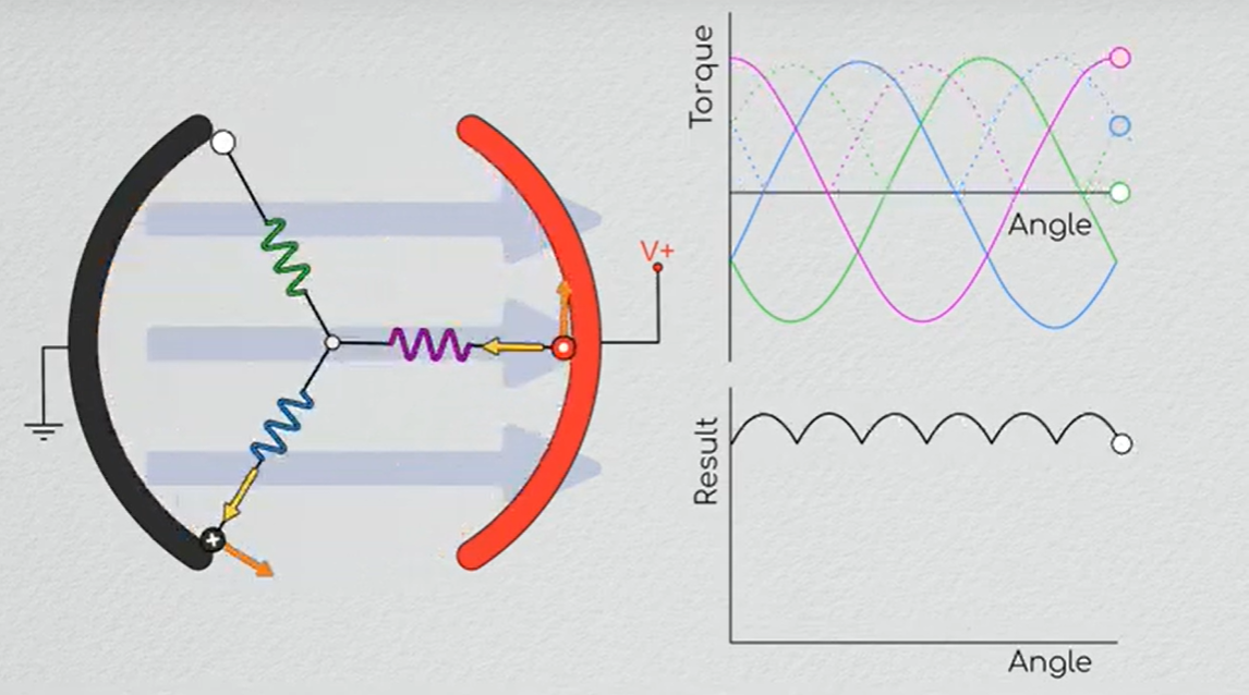 - If we plot the torque with respect to the rotation, we can see that the output torque fluctuates by about 14% periodically throughout the rotation. This fluctuation is called the Torque ripple.
- The average torque in the motor T is proportional to,
- If we plot the torque with respect to the rotation, we can see that the output torque fluctuates by about 14% periodically throughout the rotation. This fluctuation is called the Torque ripple.
- The average torque in the motor T is proportional to,
T ∝ iLdBN
where i is the current, L is the length of the motor, d is the diameter, B is the magnetic flux density and N is the number of turns of the coil.
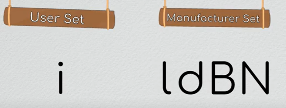
The manufacturer set parameters are constant for a motor and cannot be changed easily, they are grouped together into a constant called the Motor constant.
 - We can model the motor as a resistor, inductor, and a gyrator system
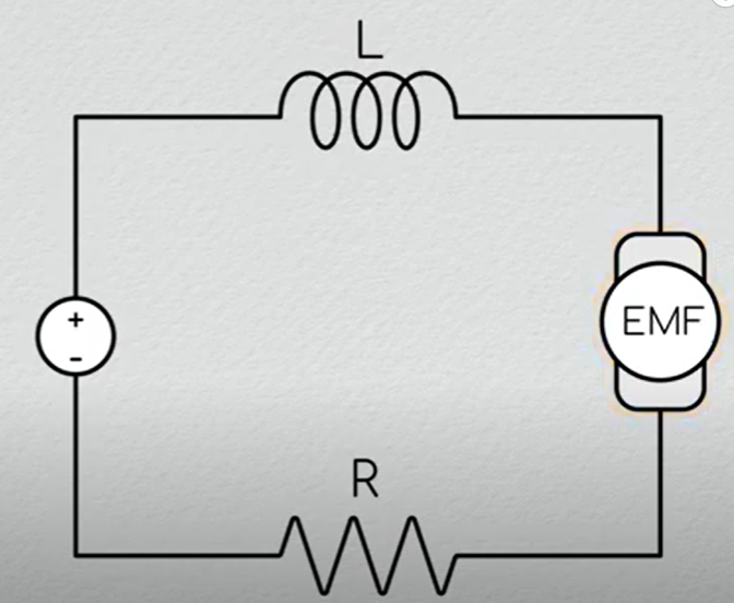 The voltage across the gyrator system is the back EMF.
- Back emf
- When the conductors of the armature cut across the magnetic field a voltage is induced in the windings. This voltage is in series with the supplied voltage but in the opposite direction.
- The direction of induced voltage is given by Fleming’s right hand rule, the index finger represents the direction of the magnetic field. The thumb shows the direction of motion of the conductor and the middle finger represents the emf induces on the conductor.
- the magnitude of the back emf is always less than the applied voltage. The difference between the two is nearly equal when the motor runs under normal conditions. Eb = V – IaRa.
- The supply voltage induces the current in the coil which rotates the armature. The electrical work required by the motor for causing the current against the back emf is converted into mechanical energy. And that energy is induced in the armature of the motor. Thus, we can say that energy conversion in the DC motor is possible only because of the back emf.
- The mechanical energy induced in the motor is the product of the back emf and the armature current, i.e., EbIa.
- The back emf makes the DC motor self-regulating machine, i.e., the back emf develops the armature current according to the need of the motor. The armature current of the motor is calculated as:
The voltage across the gyrator system is the back EMF.
- Back emf
- When the conductors of the armature cut across the magnetic field a voltage is induced in the windings. This voltage is in series with the supplied voltage but in the opposite direction.
- The direction of induced voltage is given by Fleming’s right hand rule, the index finger represents the direction of the magnetic field. The thumb shows the direction of motion of the conductor and the middle finger represents the emf induces on the conductor.
- the magnitude of the back emf is always less than the applied voltage. The difference between the two is nearly equal when the motor runs under normal conditions. Eb = V – IaRa.
- The supply voltage induces the current in the coil which rotates the armature. The electrical work required by the motor for causing the current against the back emf is converted into mechanical energy. And that energy is induced in the armature of the motor. Thus, we can say that energy conversion in the DC motor is possible only because of the back emf.
- The mechanical energy induced in the motor is the product of the back emf and the armature current, i.e., EbIa.
- The back emf makes the DC motor self-regulating machine, i.e., the back emf develops the armature current according to the need of the motor. The armature current of the motor is calculated as: 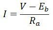 - According to Jame Watt, the power is given by the current in the system times the voltage across it.
P= VI
The electrical power that is converted to mechanical power is given by the current times the back emf
The mechanical power P=𝜔T, Hence
εI= 𝜔T
εI= 𝜔KtI
ε= 𝜔Kt
- According to Jame Watt, the power is given by the current in the system times the voltage across it.
P= VI
The electrical power that is converted to mechanical power is given by the current times the back emf
The mechanical power P=𝜔T, Hence
εI= 𝜔T
εI= 𝜔KtI
ε= 𝜔Kt
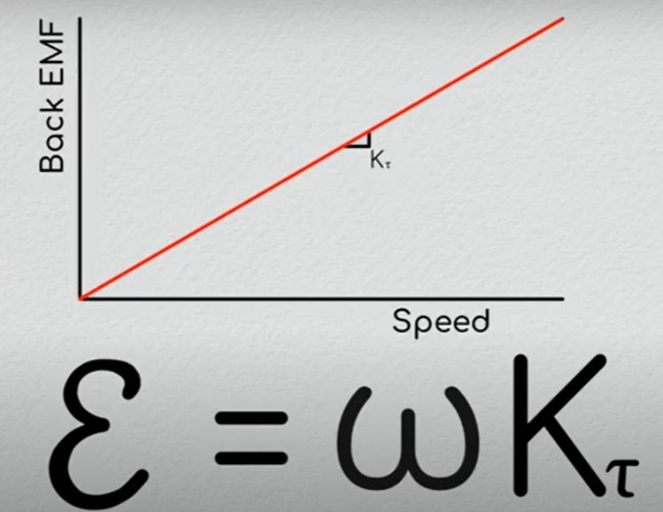
The back emf of the motor is proportional to angular velocity, as the RPM increases the EMF will also increase.
- As the back EMF increases the net voltage across the resistive element drops, hence less current can be made to flow through it. As the motor turns faster the voltage we supply become less effective at driving a current through it, meaning it will achieve a maximum terminal velocity which is equal to the supply voltage divided by the torque constant. 𝜔max = Vs/Kt (when Vs become equal to back emf)
- For a given Voltage V supplied to motor, which drives a current I through the windings, which generates a Force F=iLB, which couple to give a torque T =idLBN, which sets the motor spinning at rotational velocity 𝜔, which in turn induces a back emf ε on the windings, which opposes the voltage Vs forming an equilibrium condition where the voltage supplied is just enough to make the motor spin at the current RPM. Any load on the motor would reduce the speed, and hence the back emf, allowing voltage to push more current into the motor and bringing the speed to a new equilibrium.
- ### Controlling direction and speed
- The torque generated by the motor T= iKt, by switching the direction of the current we can switch the direction of torque.
- Since the motor is modelled as an inductor and a resistor, the inductor resists the rapid changes in current, thereby acting as a low pass filter
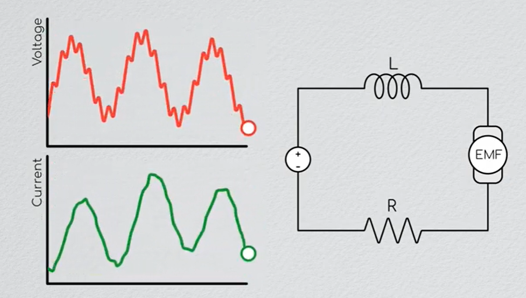 - A PWM signal is used to modulate the current in the motor, inorder to get a smooth flow, a frequency of 10-20Khz is used.
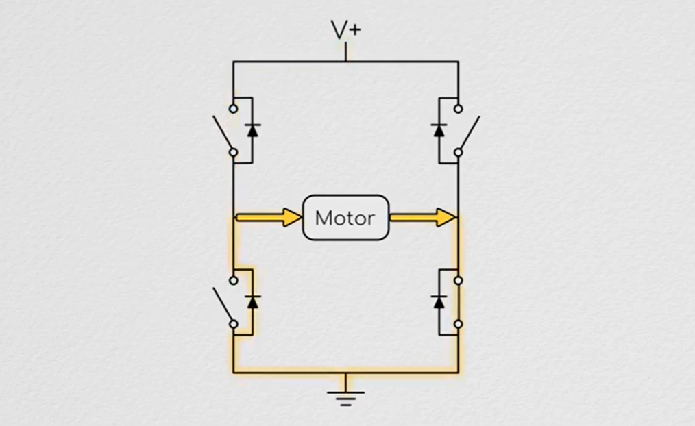
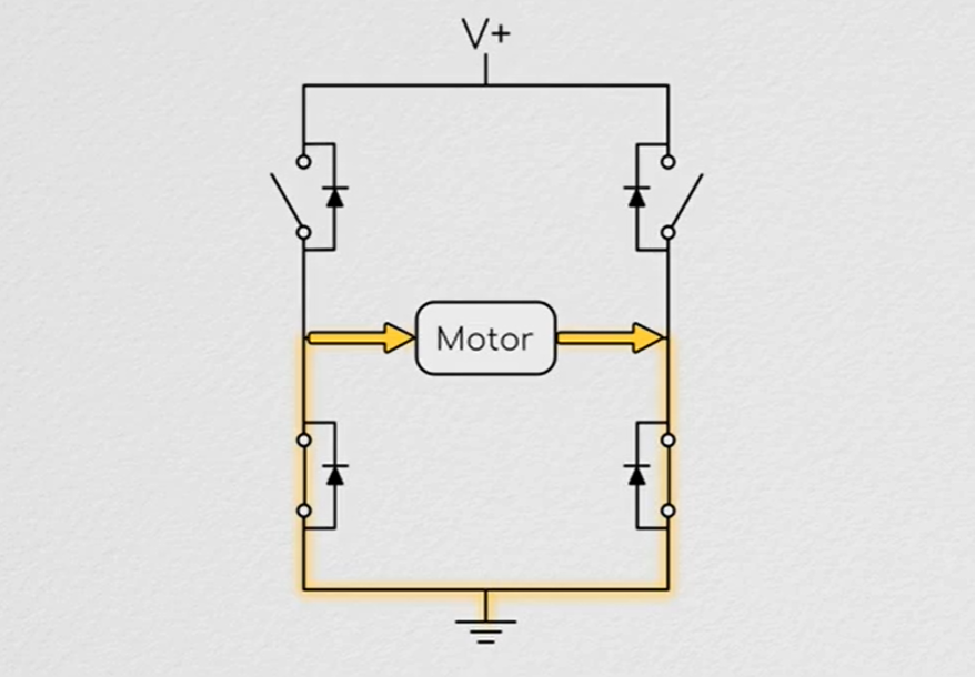
- When a current path is driven by the Hbridge, the current flows through the two switches from positive to ground
- A PWM signal is used to modulate the current in the motor, inorder to get a smooth flow, a frequency of 10-20Khz is used.
- When a current path is driven by the Hbridge, the current flows through the two switches from positive to ground
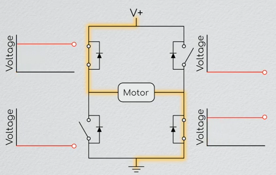 - When there is no direct current path and the current is driven by the inductance in the motor then the current goes form the ground up through the body diode of the mostfets into the positive terminal. Depending on the way we switch the H bridge we can control this behavior.
- ### How motors Fail
- Brushes in a Dc motor are the main source of wear for the motor. Brush bounce happen when the brush is moving over the commutator at high speeds, which limits how fast the motor can turn.
- Heat is the main problems with motors, as current runs through the winding, they experience Joule heating which Q= i^2R, as temperature increases the resistance also increases.
- When there is no direct current path and the current is driven by the inductance in the motor then the current goes form the ground up through the body diode of the mostfets into the positive terminal. Depending on the way we switch the H bridge we can control this behavior.
- ### How motors Fail
- Brushes in a Dc motor are the main source of wear for the motor. Brush bounce happen when the brush is moving over the commutator at high speeds, which limits how fast the motor can turn.
- Heat is the main problems with motors, as current runs through the winding, they experience Joule heating which Q= i^2R, as temperature increases the resistance also increases.
There are 4 thermal resistance in a DC motor, the Conduction from the windings to the rotor (R1), the convection from rotor to the stator (R2), the conduction form the inside of the stator to the outside (R3) and the convection/conduction from the outside of the stator (R4)
Total heat transferred Q = dT/(R1 + R2 + R3 + R4)
In a brushless motor the windings are on the stator and magnets are on the rotor, thereby eliminating the R1 and R2, which allows them to run much cooler and handle larger current.
- ### Sensing Rotation
- Hall Effect
- It is the phenomenon wherein when a magnetic field is applied such that it is non parallel with an electric current, a voltage is generated which is orthogonal to both, and is maximized when the current and magnetic field are perpendicular.
- This happens because of the #Lorentz equation force where the charge carriers are moving through a magnetic field and they experience a force, which means the charges are biased to one side of the conductor, this sets up a potential difference which can be measured across the conductor.
- 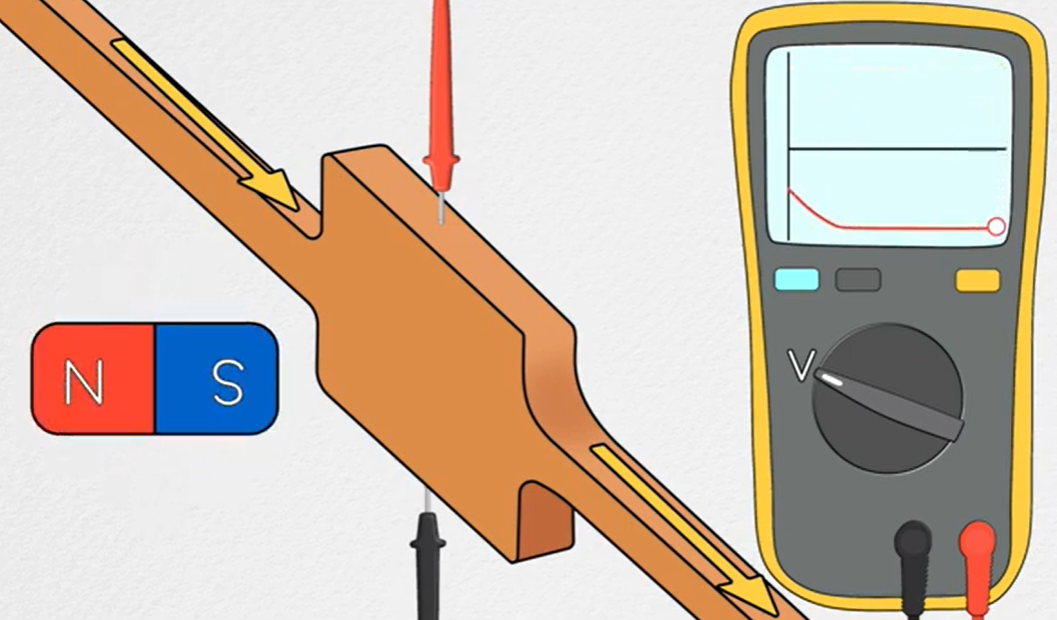 - What this allows us to do is to sense when the North pole of a magnet is facing towards the sensor or away from it.
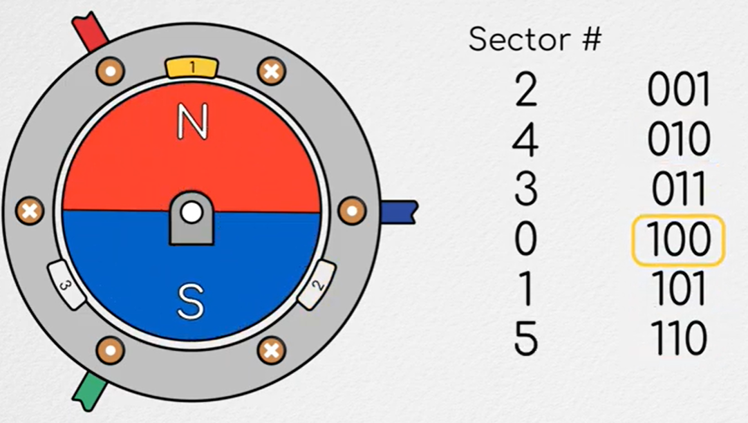
- With 3 hall sensors positioned at 120deg we can tell which of the six sectors the magnet’s north pole is in. Taking binary 1 as when the North pole is facing the sensor we can represent the six possible positions in a table.
-
- What this allows us to do is to sense when the North pole of a magnet is facing towards the sensor or away from it.
- With 3 hall sensors positioned at 120deg we can tell which of the six sectors the magnet’s north pole is in. Taking binary 1 as when the North pole is facing the sensor we can represent the six possible positions in a table.
-  - ### Alignment torque
-
- ### Alignment torque
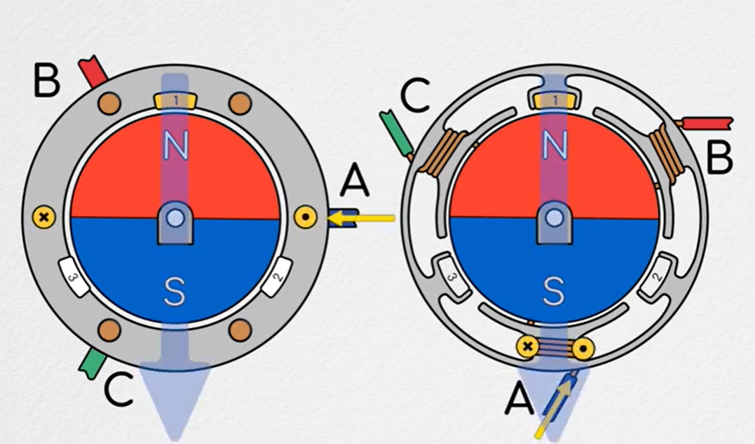
-  - When a magnet is place perpendicular to the field then the North pole will try and align itself with the field, this creates a net torque on the rotor.
- Thus we want to make sure that the magnetic field we are generating with induction in the coil will always lead the rotors magnetic field by 90deg.
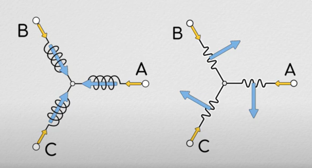
- In a brushless motor, the simplest way to visualize the magnetic field is to imagine that running a current through each winding will create a magnetic field pointing radially outwards and at the axis of the coils.
-
- When a magnet is place perpendicular to the field then the North pole will try and align itself with the field, this creates a net torque on the rotor.
- Thus we want to make sure that the magnetic field we are generating with induction in the coil will always lead the rotors magnetic field by 90deg.
- In a brushless motor, the simplest way to visualize the magnetic field is to imagine that running a current through each winding will create a magnetic field pointing radially outwards and at the axis of the coils.
-  -
- 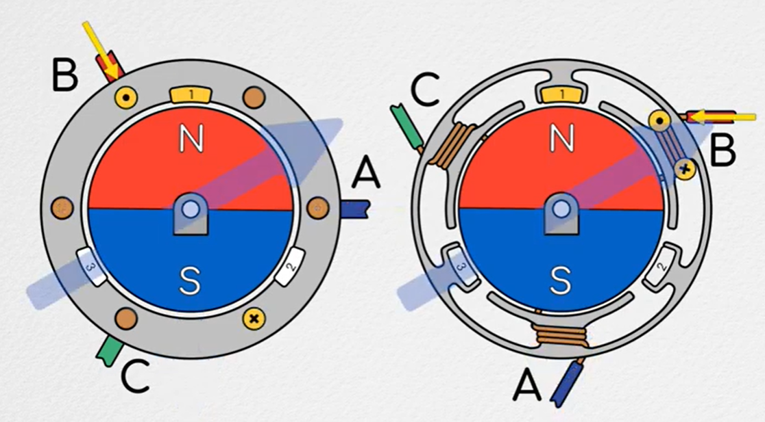 -
- 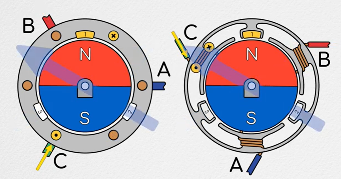 - The underlying principle is the same, induce a magnetic field that is orthogonal to and leading the rotor’s magnetic field.
- ### Commutating Brushless motors
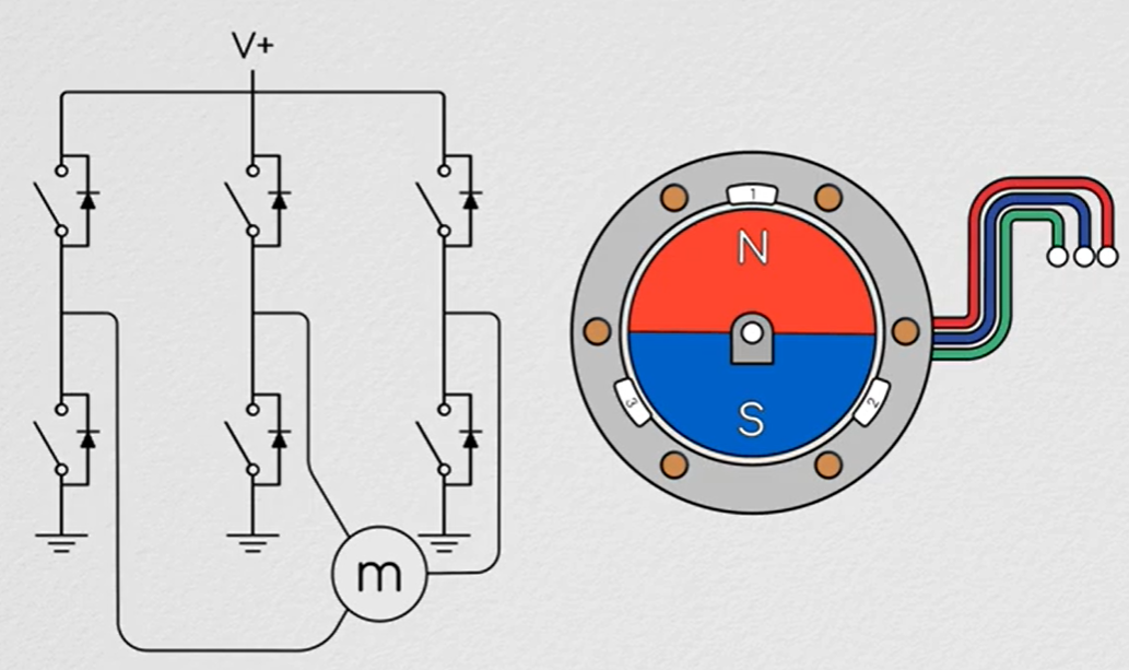
- In brushed motors we used an H bridge to modulate the current through the windings but, brushless motors have 3 windings and require 3 Half bridges to control them.
- The underlying principle is the same, induce a magnetic field that is orthogonal to and leading the rotor’s magnetic field.
- ### Commutating Brushless motors
- In brushed motors we used an H bridge to modulate the current through the windings but, brushless motors have 3 windings and require 3 Half bridges to control them.
 - Six sector Block commutation
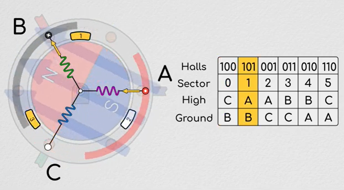 The difference here is that the magnetic field is rotated and the windings are stationary, using the information from the hall sensor we can determine the position of the rotor and turn the corresponding windings on and off
- ### Types of switching methods
- All PWM switching behaves the same in the forced phase, its how it handles in the unforced phase drastically changes the electrical dynamics and the efficiency of the system.
- Hard switching
- In the forced phase the mosfets connect the power through the motor but in the unforced phase the switches are left open.
-
The difference here is that the magnetic field is rotated and the windings are stationary, using the information from the hall sensor we can determine the position of the rotor and turn the corresponding windings on and off
- ### Types of switching methods
- All PWM switching behaves the same in the forced phase, its how it handles in the unforced phase drastically changes the electrical dynamics and the efficiency of the system.
- Hard switching
- In the forced phase the mosfets connect the power through the motor but in the unforced phase the switches are left open.
-  - Due to the inductance in the motor current will be forced to continue in the same direction, pulling current form the ground and into the positive side via the #Mosfet body Diode.
- In hard switching, the regenerative energy pulled form the ground and driven to the positive side may be used to charge the battery, but this is not efficient, as the energy that is flowing back into the sources is the same energy that was used to drive the current, this forces us to run at a higher duty cycle than necessary. Regeneration is not 100% efficient and you loose energy in the conversion process.
- It will be difficult to maintain the current with duty cycle less than 50% **as energy given is returned at the same time. This its **difficult to have accurate current control, and can be less efficient.
- Soft switching
-
- Due to the inductance in the motor current will be forced to continue in the same direction, pulling current form the ground and into the positive side via the #Mosfet body Diode.
- In hard switching, the regenerative energy pulled form the ground and driven to the positive side may be used to charge the battery, but this is not efficient, as the energy that is flowing back into the sources is the same energy that was used to drive the current, this forces us to run at a higher duty cycle than necessary. Regeneration is not 100% efficient and you loose energy in the conversion process.
- It will be difficult to maintain the current with duty cycle less than 50% **as energy given is returned at the same time. This its **difficult to have accurate current control, and can be less efficient.
- Soft switching
-  - In soft switching, after the forced phase, the right bottom mosfet is kept closed. So the current travels up from the ground, through the first body diode, and back into ground through the second mosfet.
- Complementary switching
-
- In soft switching, after the forced phase, the right bottom mosfet is kept closed. So the current travels up from the ground, through the first body diode, and back into ground through the second mosfet.
- Complementary switching
-  - Here both the lower side mosfets are kept closed after the forced phase and the current travels from left to right in the motor.
- Diode drops MOSFET
- In a diode, it offers infinite resistance in one direction and resistance that is inversely proportional to the current running through it in the other direction. This means that whether its 500ma or 5A the voltage drop over the diode will be the same.
-
- Here both the lower side mosfets are kept closed after the forced phase and the current travels from left to right in the motor.
- Diode drops MOSFET
- In a diode, it offers infinite resistance in one direction and resistance that is inversely proportional to the current running through it in the other direction. This means that whether its 500ma or 5A the voltage drop over the diode will be the same.
-  -
-  - In hard switching, the current has to travel through 2 diodes, the diode drop over each can be as much as a few volts, that means there is few volts pushing against the flow of current. Thus the current will decay much faster in hard switching, this will make high resolution current tracking much more difficult. Additionally the resistive element will drop power in terms of heat as I^2 R.
- Complementary switching is the most preferred way to switch power to a motor.
-
- ### Clark and Park Transformation
- Its helpful to have the current and the magnetic field in the same direction, so its better to model the motor as a set of coils which when current passes through them would generate a magnetic field along the same direction.
-
- In hard switching, the current has to travel through 2 diodes, the diode drop over each can be as much as a few volts, that means there is few volts pushing against the flow of current. Thus the current will decay much faster in hard switching, this will make high resolution current tracking much more difficult. Additionally the resistive element will drop power in terms of heat as I^2 R.
- Complementary switching is the most preferred way to switch power to a motor.
-
- ### Clark and Park Transformation
- Its helpful to have the current and the magnetic field in the same direction, so its better to model the motor as a set of coils which when current passes through them would generate a magnetic field along the same direction.
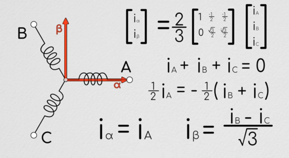
-  - This is a 2D representation as we can generate a resultant vector from just two phases, this idea of representing the equivalent induction in a 3 phase motor in two directions is **the Clark transformation. Edith Clark MIT 1919.
- The Clark transform converts the abc reference frame to that of **α β frame. Strictly, A points to the α direction, B point to the -sin60α cos60β
-
- This is a 2D representation as we can generate a resultant vector from just two phases, this idea of representing the equivalent induction in a 3 phase motor in two directions is **the Clark transformation. Edith Clark MIT 1919.
- The Clark transform converts the abc reference frame to that of **α β frame. Strictly, A points to the α direction, B point to the -sin60α cos60β
- 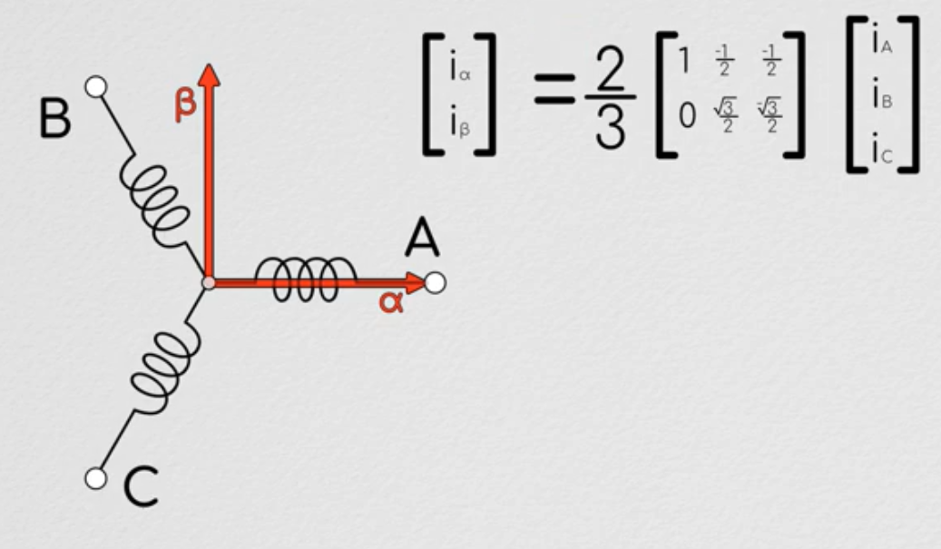 - The Clark transform also has a 2/3 constant to keep the power on both sides the same. As the system obeys krichoff’s law when we take the geometric sum the current through the A gets counted twice. But since we are only concerned with the current in the α β plane, we need to add the constant.
-
- The Clark transform also has a 2/3 constant to keep the power on both sides the same. As the system obeys krichoff’s law when we take the geometric sum the current through the A gets counted twice. But since we are only concerned with the current in the α β plane, we need to add the constant.
- 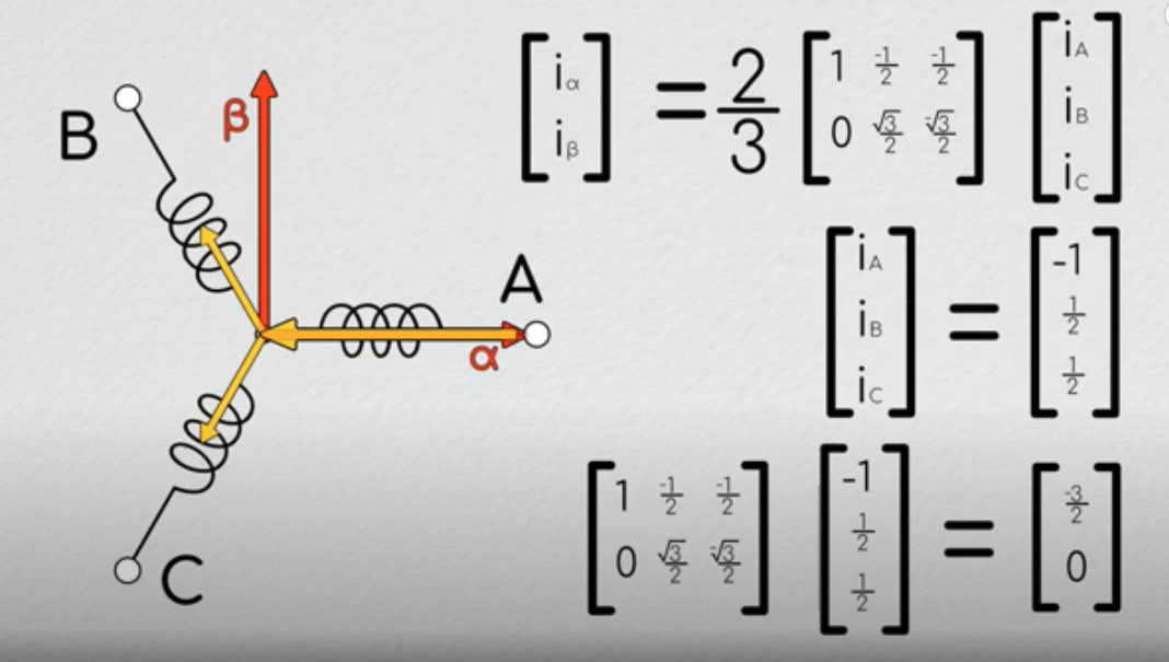 - Simplifying with Kirchhoff’s law we get the current in α β
-
- Simplifying with Kirchhoff’s law we get the current in α β
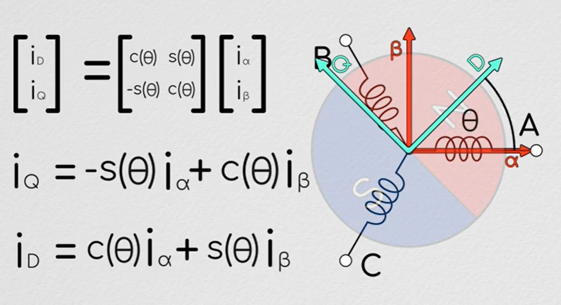
-  - We will take this two axis representation and analyze it form the perspective of the rotor using the** park transformation. By creating another reference frame that will turn with the motor, by convention the axes of these are referred to as the **Direct and Quadrature axes.
-
- We will take this two axis representation and analyze it form the perspective of the rotor using the** park transformation. By creating another reference frame that will turn with the motor, by convention the axes of these are referred to as the **Direct and Quadrature axes.
- 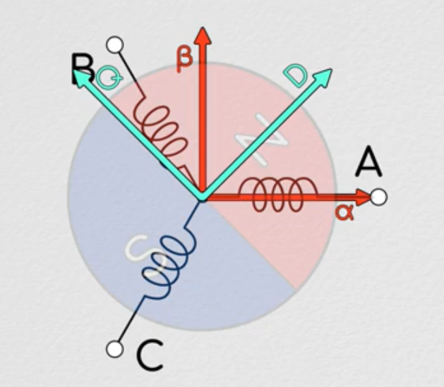 - The axis in the direction of the magnetic field is called the direct axis **and one 90deg counterclockwise to it is called the **quadrature axis.
-
- The axis in the direction of the magnetic field is called the direct axis **and one 90deg counterclockwise to it is called the **quadrature axis.
- 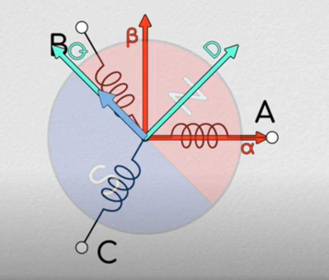 - A magnetic field produced in the positive Q direction will produce a counterclockwise torque and a field in the positive D direction will strengthen the magnetic field of the rotor.
-
- A magnetic field produced in the positive Q direction will produce a counterclockwise torque and a field in the positive D direction will strengthen the magnetic field of the rotor.
-  -
-
-
Motors
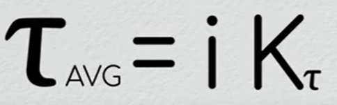
- For motors the Torque output T=Kt *I Kt is the motor constant. Which depends on the winding geometry, number of turns, etc.
- For DC brushed motors, the cheaper ones use graphite brushes, which have high friction and high wear. The high end motors like maxon uses precious metal brushes which have low friction and last a long time. This is important in haptics as the frictional forces between the brushes will limit the minimum force that can be applied by the motor.
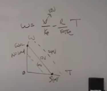
- For steady state this is the line a DC motor behaves. The bottom right condition is the stall and the top left is the no load speed. Keep in mind that **every time your motor starts up, its starting form the stall condition. **So spec current to meet the stall condition.
- The way to control a motor is, the control loop sends a voltage to the motor amplifier. The amplifier receives the voltage and turns it into current through something called Transconductance which is how the ratio of current change to the voltage change in an electronic system. Which sets up a closed loop current in the motor coil, with the set point given by the voltage applied.
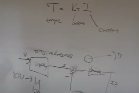
- This is the easiest way to drive motors but nobody does this. All the industrial guys use Voltage drives.
- The two main types of control used are
- Force control T=Kt*I you need special current sources for them.
- Voltage drives, you use PWM to generate voltage output to command motors.
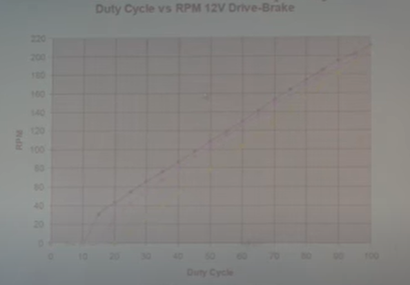
- Duty cycle of the PWM vs RPM of the motor. running at higher frequency 20Khz is better as it gives better linear relationship of the PWM with RPM. There will always be a dead band near the low end of the duty cycle.
- The time it takes current to go from 0 to 63.2% is the time constant T=L/R, L inductance, R Resistance.
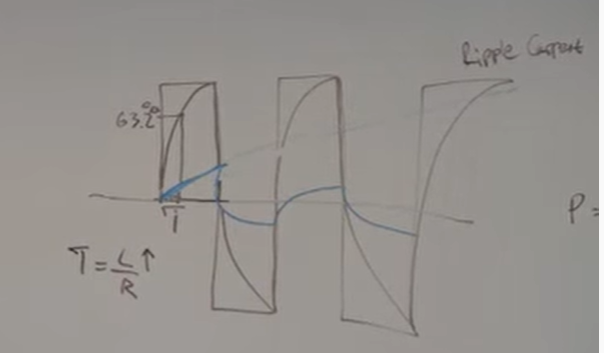
- When we are doing force control with a DC motor by controlling the current, we want to keep the motor current in a stable position. The** time constant defines how fast the current rises** in the motor. Any current over the mean value is wasted as I^2R heating losses. So if we want smooth control of current we need to increase the time constant. For this we will use inductors in series with the motor terminals.
- This will smooth the current wave forms and keep the motor current near the mean value.
- Everyone who does haptics uses ‘RE’ series maxon motors and Copley amps. **The Copley amps is a closed loop current controller, It will explode if we don’t give a time constant within the bands they accept. The problem is that for similar torque ranges the maxon motors will have very low inductance even for the same resistance. **
- Two things can happen if you plug your maxon motor to your Copley amps,
-
- The motor will heat up fast as the time constant is very low and there will be ripple currents.
-
- The current control in the copley explodes and the motor starts spinning infinetly.
-
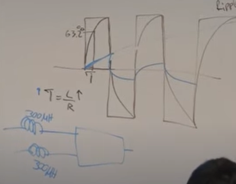
- The solution is to use two inductors in series, typically 300mH each.
- Practically you are slowing down your electrical dynamics so that you are stable in torque speed region, after that you have the rest to work on your servo loop.
- Maxon motor RE series have part numbers form RE 40/30/10 the number defines the outer diameter. Careful when using a RE-10 the smaller the motor, the smaller the wires and the resistance goes up. That means the 300mH will not be enough and you will burn the motor instantly.
- Never design your parts around the CAD models provided by any manufacturer. The bible is the spec sheet provided with the part.
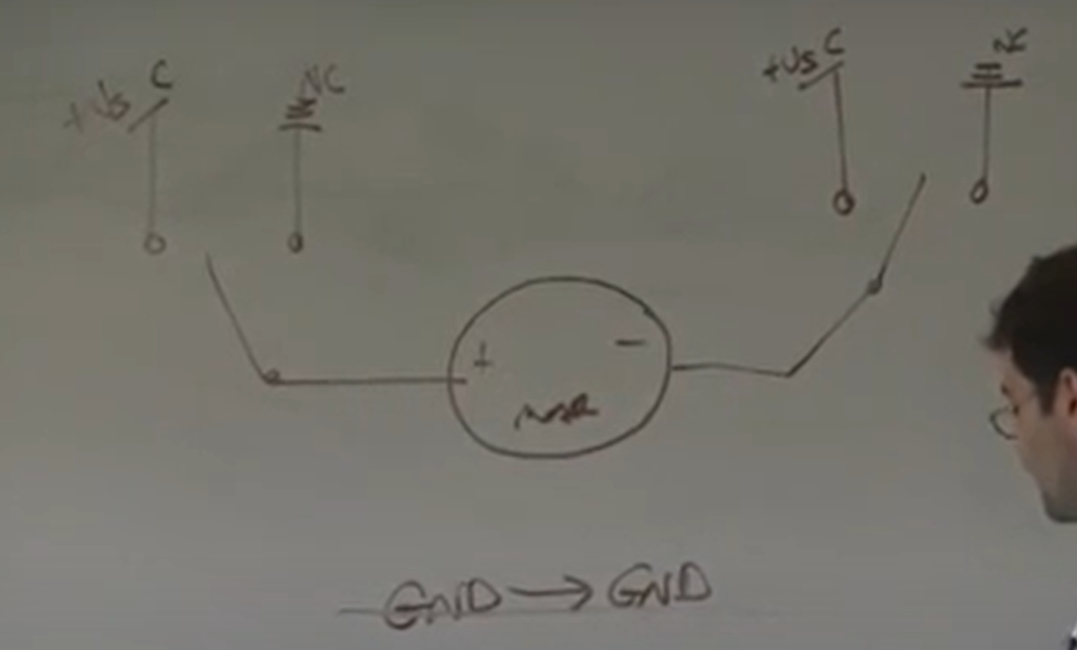
- An easy way to run DC motors manually get SPDT single pole dual throw switch. They are normally connected to the NC side. when you press one, you connect ground to Vs and vice versa. when you press both nothing happens as its either connected to ground on both side or Vs.
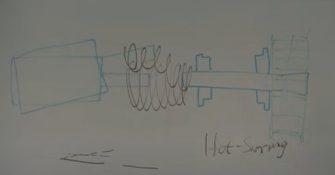
- Reasons to use a flexible shaft coupling,
- You don’t want any radial loading on the motor.
- If you put the pulley on the motor then if you want to take off the encoder and motor then you will have to remove your whole belt assembly.
- Takes ups the angular and axial misalignment.
- With this method you can **Hot swap **the motor, say an RE 30 was not big enough, then you remove the motor and put an RE40 without disturbing the rest of the setup.
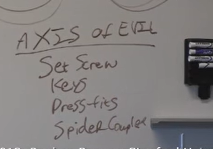
- Don’t use spider couplers, good helical couplers are best.
- Don’t get the ones with set screws, once you tighten and run the motor for 5 mins they will back out and fall into your machine. If you are unlucky they will get in between your gear and the slides.
- For a given size set screws have a higher torque transmitting capacity than clamps. If the manufacturer does not list the max torque for the clamps, don’t buy them. If you need a small coupler and high torque capacity, use a set screw.
-
Motor Cogging
- DC motors have discrete positions where are stable and it takes a small amount of torque to take them out of these positions.
- Cheap motors will have a ferrous core with high magnetic permeability and over time develop a slight magnetic field. This interacts with the stators magnetic field causing cogging.
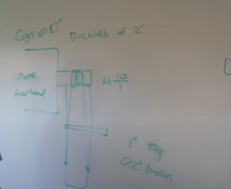
- Gear and cable transmission **are not only for speed reduction, you can use them **effectively to take the bad performance out of a motor.
- Say you want a 100:1 gear ratio, its better to split it into two parts, say a compact 10:1 gear on the motor and a compact 10:1 capstan drive, this will take out the backlash in the gears and you will have higher resolution.
- The larger gearbox would have say 2deg of backlash, but putting a 10:1 capstan on top of it effectively reduces the backlash to 0.2deg.
- The cleanest way to get more torque is to have bigger motors.
- Make sure that you are not using the motor near the peak currents as you will torch them. Maxon provides specs for if you use the motor near stall, how long you have to let it cool before you can use it again.
- Motors have max axial and radial forces, do not exceed that. Never pressfit onto the motor shaft, they are difficult to get on and remove. All the details of how you put the pulleys matters.
-
Stepper Motor
- Lin engineering custom stepper and BLDC motors
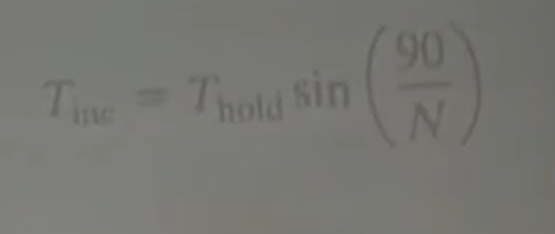
- Tinc is the incremental torque, Thold max torque and the N is the micro steps. So full step N is 1 and sin(90) is 1. If we microstep to 16 the only torque we have available is down to 9.85%
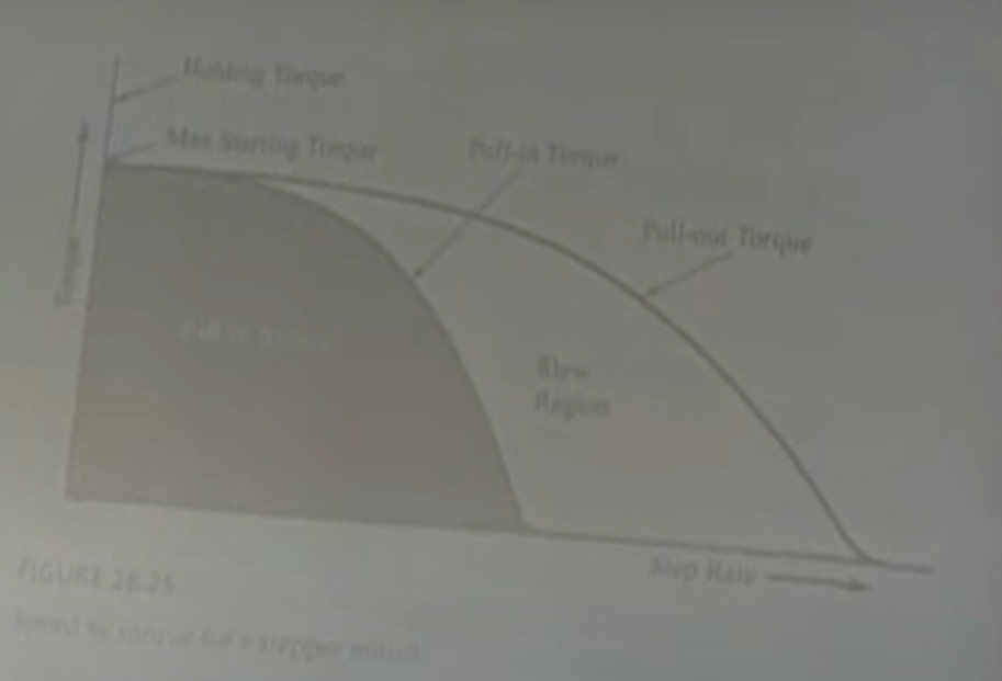
- Torque vs slew rate(velocity) two main curves, pull in torque and pull out torque.
- The pull in torque region any torque and velocity is possible. The pull out torque is the maximum it can give without skipping steps. The slew region is where the torque and speed are attainable but not instantaneously, there is starting and stopping inertia.
- Why does the torque curve fall off? well its a giant inductor and the faster we move the less happy the inductor is and you will not be able to achieve full current, running at higher voltages can help decrease the rise time.
-
Gear motor
- Spur gear motors usually have off-center axis, planetary gear motors have large power densities.
- Reflected inertia of gear motor is N^2. Jo = N^2 Ji, Jo is the inertia at output.
- The friction at the output Fo = N*Finout, where N is the gear ratio.
- Exponential decrease function when plotting gear ratio and back drivability.
-
tags: CNC Motors #Stepper Motor
- Tags: CNC Motors #Servo Stepper