Deckel Maho DMU 60T
- tags Milling Fabrication
- Resources
- Heidenhain Mill plus IT manual German
- Heidenhain Mill plus V600 Manual Eng
- CNC coding guide Millplus IT DMU
- Webarchive Mitllplus trainer
- Machine Manuals
- Change machine constants
- TNC640 series
- Matal Swiss DMU demo and tests
- TNC530 tutotials
- TNC640 tutorials
- CNC training Center
- Cad cam tutorials
- Millplus simulation
- Tooling and Machine settings
- Notes
-
Change Machine constants
- Parameter to change language is MC5. 0 is german, 1 is english. **To change language press Emergency Stop. Switch 19S1 in electric cabinet on. Change parameter 5. Switch back 19S1 to off. Wait until control is restarted. Switch off and on the machine on main switch. If the control is not full in english you must change PLC Software. (not for DMU 60 maybe another one)**
- Here are the mini instructions: control, then enter machine constants, “1234”, press “enter”, change constant(s), save and back to the manual. reboot and everything works as it should.
-
Post Process
- Use MIllplus IT generic in Fusion 360, Edit postprocessor line 20 to change extenstion from nc to pm. DMU accepts only pm.
- Editing Post Process NYCNC
- Heidenhain ISO Gcodes
- G90 Absolute Dimensions
- G94 Feed per Minute Mode
- G17 XY plane
- G71 Millimeters
- G99 With tool number T, length L, radius R
- G98 Set Label number
- G74 Slotmilling
-
Starting the Machine
- Main ON
- Release EMERGENCY STOP switch.
- Machine ON (keep key depressed) and press CLEAR on keyboard.
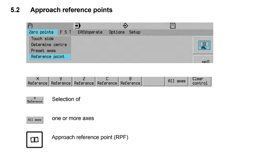
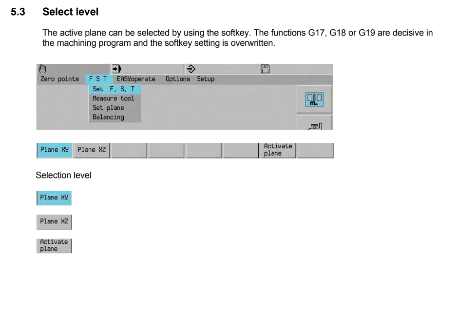
- Plane selections handles by G17, G18, G19 are used when making a circular interpolation by the machine and it needs to know which plane to make the circle.
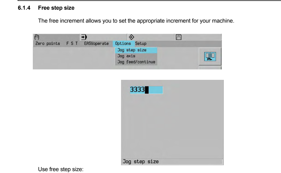
- Continous , step or free step size for jogging.
-
Programming the Heidenhain Mill plus
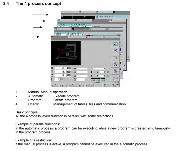
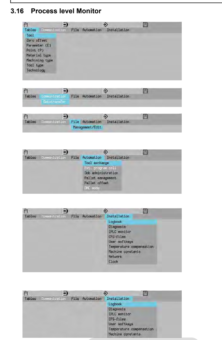
- To exit a function press the Menu again or switch to a new process
- **M0 **Interruption of program execution **M1 **Optional program stop, The stop at M1 is only executed, however, if the Selective Wait soft key is active.
- **M30 **End of part program Completing the part program execution with return to the beginning of the program.
-
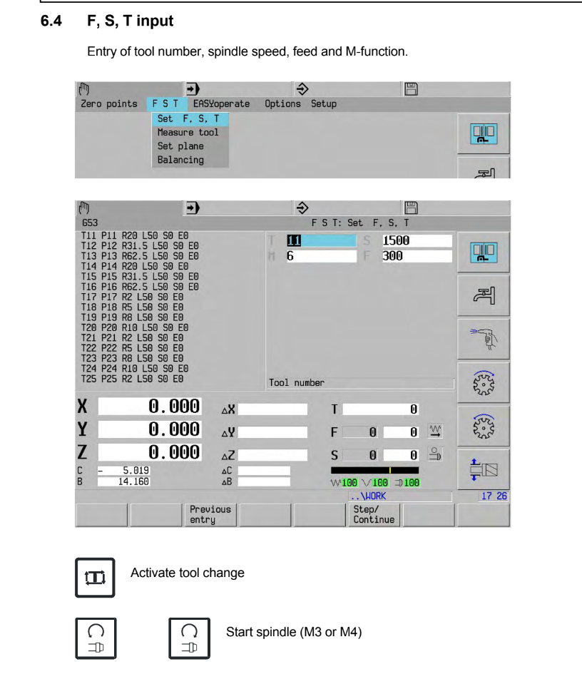
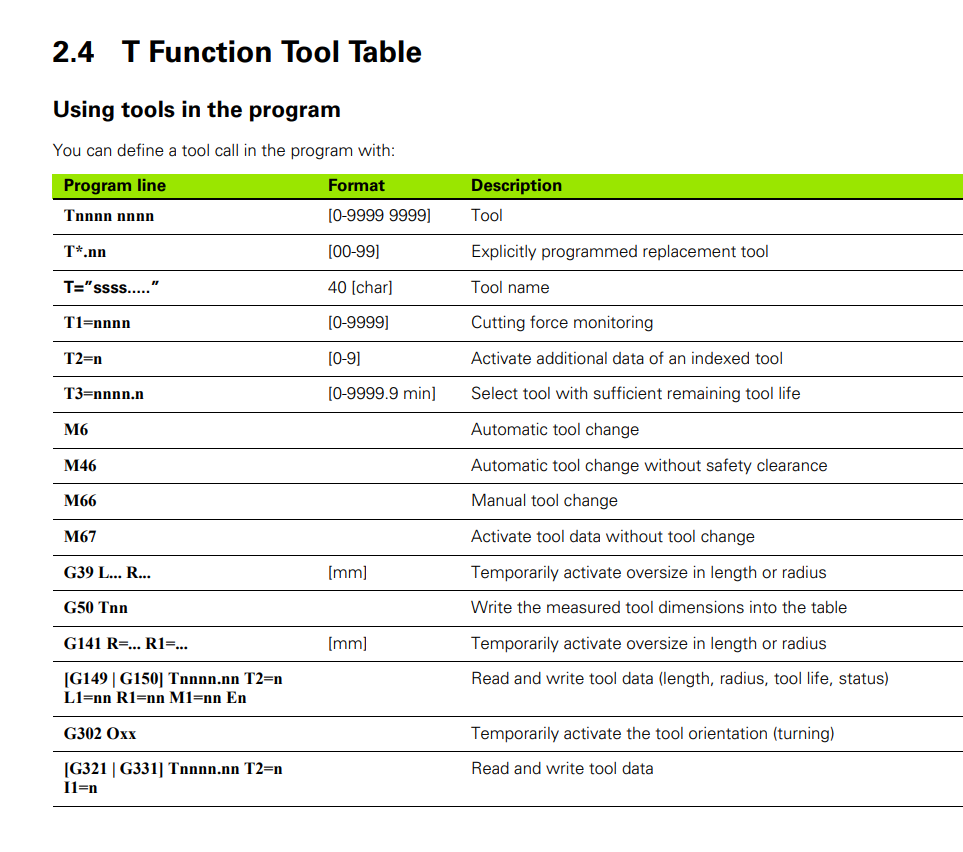
Tool
- T12 M6 **Tool number followed by M6 for automatic tool change With **T0 M6 **the **tool is removed from the spindle and returned to the magazine.
- If no T word is programmed in the M6 block, the tool that was last programmed is inserted and activated. It is recommended that you always program the tool number T for an M6 tool change.
-
Replacement tools
- A replacement tool is inserted if the tool life of the current machining tool expires or if the lowest performance limit of cutting force monitoring is exceeded. The replacement tool is identified by the two-digit number after the decimal point. The replacement tool with the lowest number is selected unless it is blocked. Otherwise, the replacement tool with the next higher number is used. The tool table contains, for example, tool T100.00 with the replacement tools T100.01 and T100.02. During an automatic tool change (M6), T100.00 is inserted (T100.00 M6). The replacement tool log is now active. If T100.00 is blocked, a replacement tool is automatically inserted. (T100.01).
- Tool Life
- Each tool is assigned a certain tool life. Whenever a tool is in use, its life is reduced by the cutting time. When the tool life has expired a warning is generated. Programming T3= selects the tool whose remaining life is sufficient. If no tool with sufficient remaining life can be found, the MillPlus generates an error message.
-
Change Machine constants
T1234 T3=12 M6
A program block T3=12 leads to the insertion of tool
number 1234, where the remaining tool life has to be
at least 12 minutes.
- M66 Automatic tool change
Interrupt the program execution for a manual tool change.** M66 is used for tools that are not in the tool magazine A tool may first have to be removed from the spindle (with T0 M6) and
returned to its place in the magazine. It may also be necessary to program a return to a position at which the tool can be inserted.The tool is changed before the tool movement programmed in the
same block is executed.
- M67 Changing the tool data Activating tool data without a tool change
- **M8/M7 Coolant no. 1/2 ON, external/internal coolant supply
- M9 Coolant no. 1 and/or 2 OFF
M13 Coolant no. 1 together with spindle ON clockwise
M13=M3+M8
M14 Coolant no. 1 together with spindle ON counterclockwise
M14=M4+M8
-  - E parameters permit a more flexible use of the programs. With a single
program you can manufacture different workpieces by changing the
parameter data contained in the CNC’s parameter memory.
With the help of macros, high-level language and E parameters, a
problem can be solved in a general way, e. g. measuring a hole with
three or four points. The parameters receive their current values
during execution, and the subprogram is adjusted to the special
program requirements.
-
- E parameters permit a more flexible use of the programs. With a single
program you can manufacture different workpieces by changing the
parameter data contained in the CNC’s parameter memory.
With the help of macros, high-level language and E parameters, a
problem can be solved in a general way, e. g. measuring a hole with
three or four points. The parameters receive their current values
during execution, and the subprogram is adjusted to the special
program requirements.
-  - Setting Tool offset
- Ways to optimize tool lenght offsets
- Tool Offsets can be either Positive or Negative.
- T15 M6; (TOOL CHANGE)
- G0 G54 G90 X1.0 Y1.5 S1500 M3;(APPLY WORK OFFSET, MOVE TO THE FIRST POSITION, TURN ON THE SPINDLE)
- G43 Z2.0 H15; (APPLY TOOL LENGTH OFFSET WHILE MOVING TO 2.0” ABOVE THE PART)
- G0 Z0.1 M08;(MOVE TO FEED HEIGHT AND CARRY ON WITH THE PROGRAM..)
-
- Setting Tool offset
- Ways to optimize tool lenght offsets
- Tool Offsets can be either Positive or Negative.
- T15 M6; (TOOL CHANGE)
- G0 G54 G90 X1.0 Y1.5 S1500 M3;(APPLY WORK OFFSET, MOVE TO THE FIRST POSITION, TURN ON THE SPINDLE)
- G43 Z2.0 H15; (APPLY TOOL LENGTH OFFSET WHILE MOVING TO 2.0” ABOVE THE PART)
- G0 Z0.1 M08;(MOVE TO FEED HEIGHT AND CARRY ON WITH THE PROGRAM..)
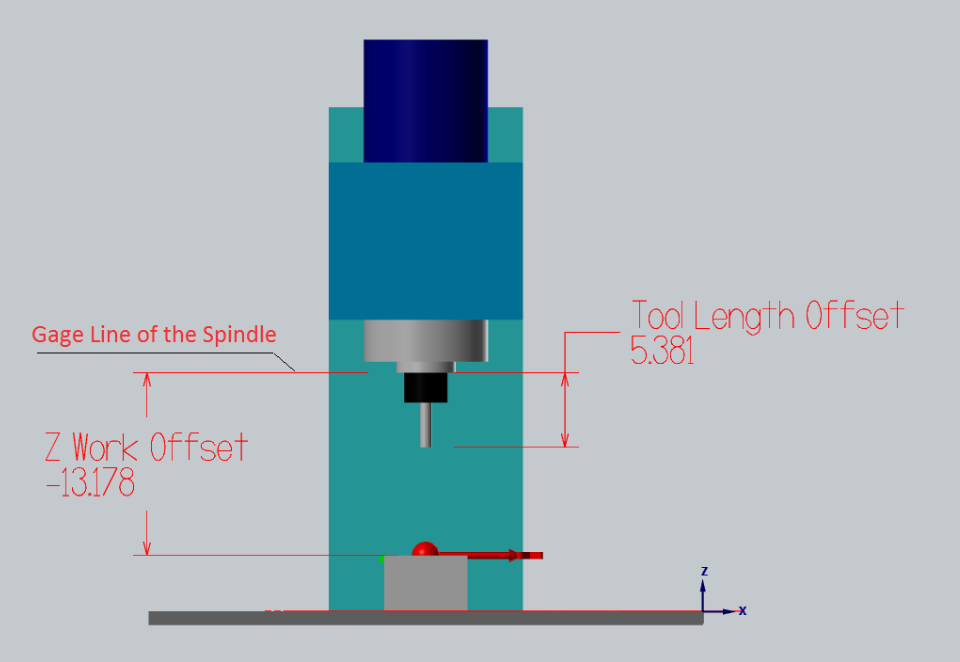
-  - Positive Tool Offsets (gage line tool length offsets)
- The offset represents the Length of the tool measured as a distance from the Gauge Line of the spindle (typically spindle nose) to the tip of the tool. The longer the tool, the larger your Tool Length offset will be.
- Part Z Work Offset will represent the distance between the same Gage Line to the top of the part.
-
- Positive Tool Offsets (gage line tool length offsets)
- The offset represents the Length of the tool measured as a distance from the Gauge Line of the spindle (typically spindle nose) to the tip of the tool. The longer the tool, the larger your Tool Length offset will be.
- Part Z Work Offset will represent the distance between the same Gage Line to the top of the part.
-  - Tool Length Offset remains the same between many machines.
- Positive Tool Offsets can be measured offline on a pre-setter and then tools can be quickly loaded into the machine without the need to tough off each tool on the machine individually.
- You are forced to operate with large negative Z Work Offset values
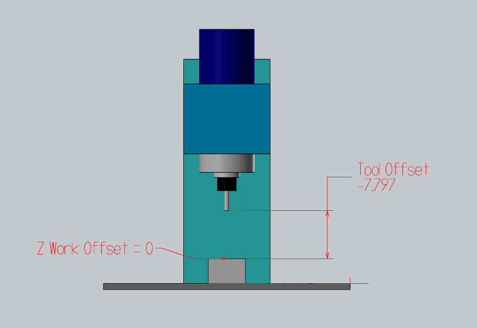
- Negative Tool Offsets
- it represents the (negative) distance between the tip of the tool to the top of the part. In such case Z Work Offset will equal zero:
-
- Tool Length Offset remains the same between many machines.
- Positive Tool Offsets can be measured offline on a pre-setter and then tools can be quickly loaded into the machine without the need to tough off each tool on the machine individually.
- You are forced to operate with large negative Z Work Offset values
- Negative Tool Offsets
- it represents the (negative) distance between the tip of the tool to the top of the part. In such case Z Work Offset will equal zero:
-  - The initial Top Of Part flat surface is often faced and filler gage is used to set the tool of the top of it.
- Dead-simple. Tool Offset represents the distance between the top of the part and the tip of the tool.
- This Tool Offset setting style is supported by default on most machines. Just jog the tool to the Top of Part and press “Write Offset”
- Tools need to be re-touched for each and every job whenever the height of the part changes
- Tool offsets are not interchangeable between several machines
- The part needs to be faced in order to set the tool offsets
- Can not set tool offsets off a curved or irregular surface: Imagine you need to rework an already machined part. How will you set the tool heights?
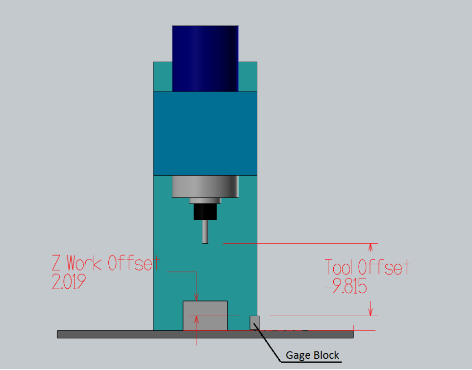
- Top of Gage Block Negative Tool Offsets:
- You can Touch Off all your tools of a pre-defined gage block off the top of your table or ground vice surface.
-
- The initial Top Of Part flat surface is often faced and filler gage is used to set the tool of the top of it.
- Dead-simple. Tool Offset represents the distance between the top of the part and the tip of the tool.
- This Tool Offset setting style is supported by default on most machines. Just jog the tool to the Top of Part and press “Write Offset”
- Tools need to be re-touched for each and every job whenever the height of the part changes
- Tool offsets are not interchangeable between several machines
- The part needs to be faced in order to set the tool offsets
- Can not set tool offsets off a curved or irregular surface: Imagine you need to rework an already machined part. How will you set the tool heights?
- Top of Gage Block Negative Tool Offsets:
- You can Touch Off all your tools of a pre-defined gage block off the top of your table or ground vice surface.
-  - if the offset table is cleared, then every offset is 0, you won’t crash a tool. In other words, the negatives make the spindle move towards the work, less negative is further from the work. Negatives are often more natural when referencing via touch off.
- Z Work Offset will equal the distance between the top of the touch-off gauge and the top of your part.
- when machining in a vise the part stick-out is the most important value, it is easy to calculate the proper Z Work Offset height.
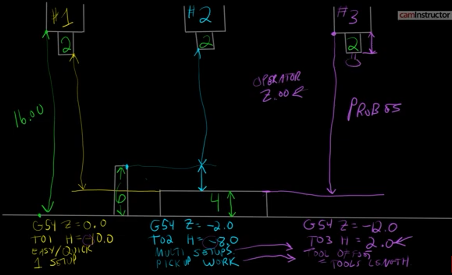
- All you have to do is set your Z Work Offset to -2.0 (in the case when you tough your tools 2” above the top of the jaw) and then add the height of your part above the vice.
- The same tools can be used without the need to re-set their Tool Offsets between jobs. Only your Z Work Offset changes.
- if the offset table is cleared, then every offset is 0, you won’t crash a tool. In other words, the negatives make the spindle move towards the work, less negative is further from the work. Negatives are often more natural when referencing via touch off.
- Z Work Offset will equal the distance between the top of the touch-off gauge and the top of your part.
- when machining in a vise the part stick-out is the most important value, it is easy to calculate the proper Z Work Offset height.
- All you have to do is set your Z Work Offset to -2.0 (in the case when you tough your tools 2” above the top of the jaw) and then add the height of your part above the vice.
- The same tools can be used without the need to re-set their Tool Offsets between jobs. Only your Z Work Offset changes.