Milling
- tags ProtoTrak Mill DPMRX2 Milling Machine Endmill Feeds and Speeds Desktop Mills Deckel Maho DMU 60T
- Resources
- Student shop pratt duke
- Fusion 360 milling workflow
- Fusion 360 fundamentals of Milling
- Manufacturing Processes 4-5 OpenOregon Fabrication #Manufacturing Processes #Design for Prototyping
- Sandvick Knowlegde Milling
- Sandvik Metal cutting E-learning
- Harvard milling tutorial
- Machining tutorials
- Selecting Milling tools
- Intro to milling tools and their application
- Homeshop tech articles Turning
- Harvey High efficiency milling Guide book
- Harvey tools Guide book and articles
- High efficiency milling HSC/HPC high speed performance cutting parameters
- Tutorials
- Fusion 360 stock contours
- Mold side milling
- Rob lockwood Fusion Cam
- Slotting with Small endmills harvey More flute counts, stronger core, low axial depth, treat like high feed mill.
- Beginner’s guide to CNC bits
- Cutter Comp
- Builds
- Granite surface table based CNC mill Vibration testing, laser interferometer, stiffness testing.
-
Notes
- Setting Tool offset
- Ways to optimize tool lenght offsets
-
Tool Offsets can be either Positive or Negative.
- T15 M6; (TOOL CHANGE)
- G0 G54 G90 X1.0 Y1.5 S1500 M3;(APPLY WORK OFFSET, MOVE TO THE FIRST POSITION, TURN ON THE SPINDLE)
- G43 Z2.0 H15; (APPLY TOOL LENGTH OFFSET WHILE MOVING TO 2.0” ABOVE THE PART)
- G0 Z0.1 M08;(MOVE TO FEED HEIGHT AND CARRY ON WITH THE PROGRAM..)
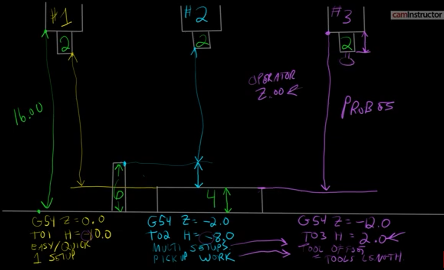
- Positive Tool Offsets (gage line tool length offsets)
- The offset represents the Length of the tool measured as a distance from the Gauge Line of the spindle (typically spindle nose) to the tip of the tool. The longer the tool, the larger your Tool Length offset will be.
- Part Z Work Offset will represent the distance between the same Gage Line to the top of the part.
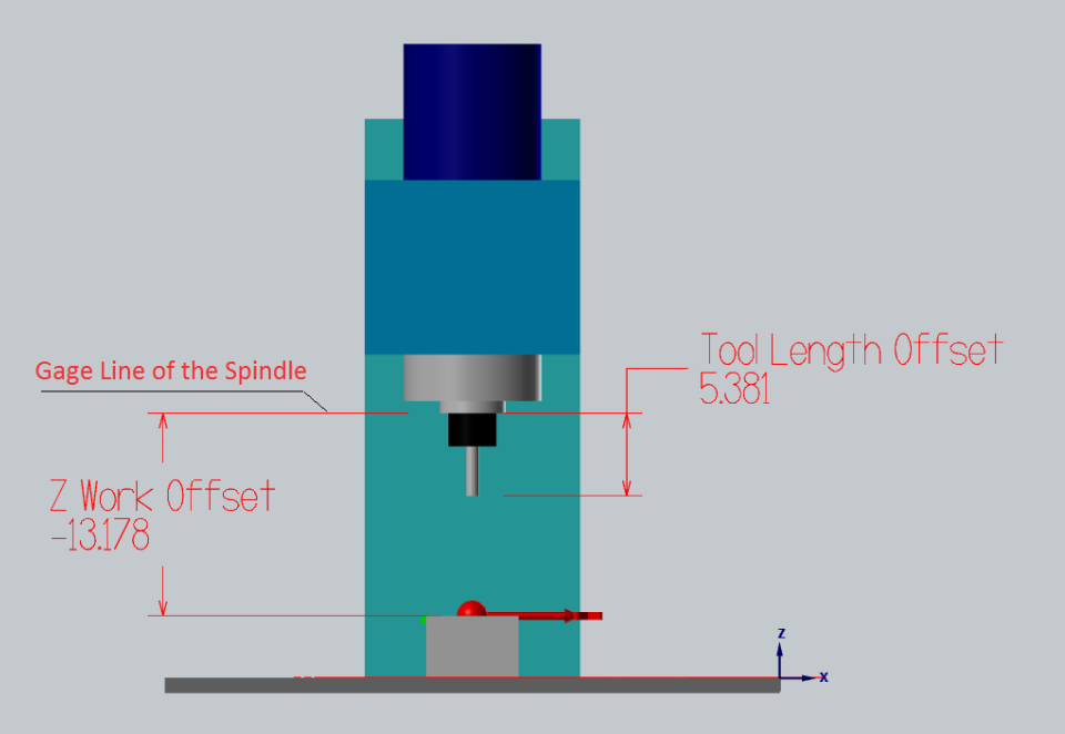
- Tool Length Offset remains the same between many machines.
- Positive Tool Offsets can be measured offline on a pre-setter and then tools can be quickly loaded into the machine without the need to tough off each tool on the machine individually.
- You are forced to operate with large negative Z Work Offset values
- Negative Tool Offsets
- it represents the (negative) distance between the tip of the tool to the top of the part. In such case Z Work Offset will equal zero:
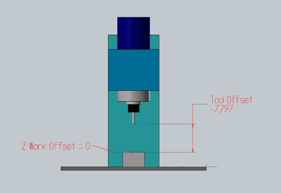
- The initial Top Of Part flat surface is often faced and filler gage is used to set the tool of the top of it.
- Dead-simple. Tool Offset represents the distance between the top of the part and the tip of the tool.
- This Tool Offset setting style is supported by default on most machines. Just jog the tool to the Top of Part and press “Write Offset”
- Tools need to be re-touched for each and every job whenever the height of the part changes
- Tool offsets are not interchangeable between several machines
- The part needs to be faced in order to set the tool offsets
- Can not set tool offsets off a curved or irregular surface: Imagine you need to rework an already machined part. How will you set the tool heights?
- Top of Gage Block Negative Tool Offsets:
- You can Touch Off all your tools of a pre-defined gage block off the top of your table or ground vice surface.
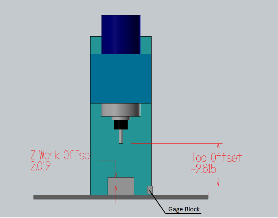
- if the offset table is cleared, then every offset is 0, you won’t crash a tool. In other words, the negatives make the spindle move towards the work, less negative is further from the work. Negatives are often more natural when referencing via touch off.
- Z Work Offset will equal the distance between the top of the touch-off gauge and the top of your part.
- when machining in a vise the part stick-out is the most important value, it is easy to calculate the proper Z Work Offset height.
- All you have to do is set your Z Work Offset to -2.0 (in the case when you tough your tools 2” above the top of the jaw) and then add the height of your part above the vice.
- The same tools can be used without the need to re-set their Tool Offsets between jobs. Only your Z Work Offset changes.
- Milling Two sides parts
- cleaning aluminum from bits use sodium hydroxide and water in ratio 1:6 and dip bit in the solution till clean.
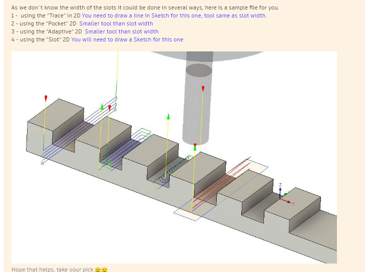
- Slotting
-
Improving surface finish #Fusion 360 CAM
- The main thing is the tool should cut a consistent amount of material in the finishing tool pass to clean up the surface.
- The coolant need to be in the right concentration to provide lubrication and free from micro debris, that can act as abrasives.
- Use adaptive to rough out the part, switch to the finish endmill and use adaptive to do another pass to reduce the staircase effect.
- Use Fusion Cam Parameters to edit the cam toolpaths and constrain the gemoetry.
-
Best Practices for Milling
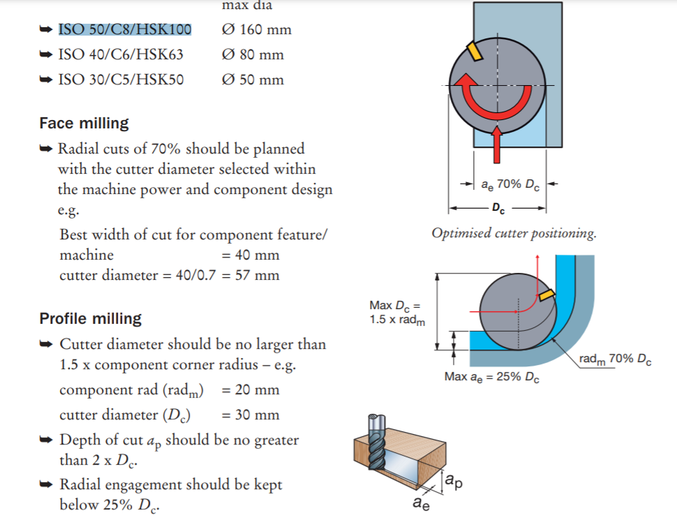

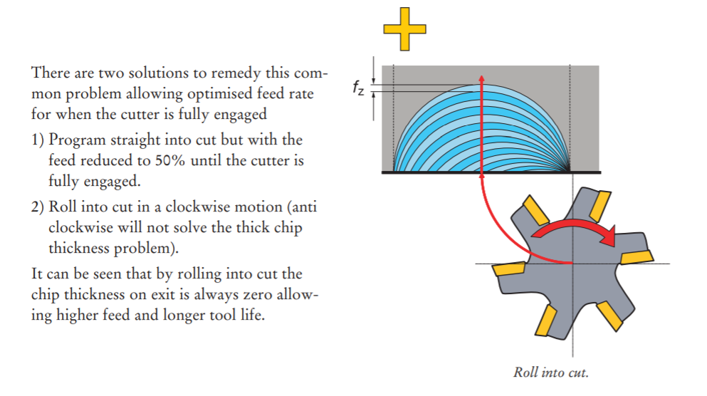
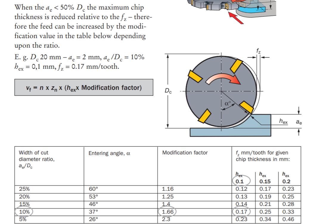
- With κr 90° long edge cutters on ISO 50 spindles and long overhang it is best to use: ➥ Low radial immersion – max ae = 25% De ➥ High axial cut – max ap = 100% D


-
High Efficiency Milling
-
Machining Aluminum
- Aluminum Machining Harvey tools
- Aluminum tends to make larger chips. Fewer flutes means more space to evacuate them. 2-3 flutes are better.

- End mills with higher helix angles will wrap around the tool faster and makes for an aggressive cut.
- Chip breaker tooling also helps with controlling the chip behaviour.
- For cast aluminum alloys (i.e. 308, 356, 380), surface footage of 500-1000 SFM is recommended, with RPMs varying based on cutter diameter. The basic calculation to find a starting point for RPMs would be (3.82 x SFM) / Diameter.
- In wrought aluminum alloys (i.e. 2024, 6061, 7075), a surface footage of 800-1500 SFM is recommended, with the same calculation being used to find a starting point for RPMs.
-
Cutter Compensation G40, 41, 42 #G code
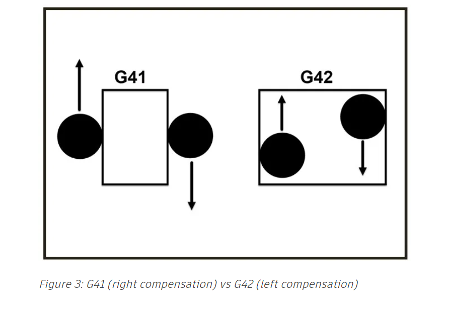
- Cutter compensation allows a way to adjust the tool path at the machine to adjust for the tool diameter, wear, and deflection.
- It allows one to program the path along the features than offsetting the features for the tool size.
- Cutter comp turns on or off with a line move, but never an arc. Commanding G40/G41/G42 with an arc move will cause a diameter compensation error that will stop the program. The line move needs to be longer than the radius of the tool in the diameter offset table of your machine control.

-
In computer
- The path is offset by the radius of the tool selected, mostly used in roughing operations with a 0.5mm stock to leave option.
-
In Control
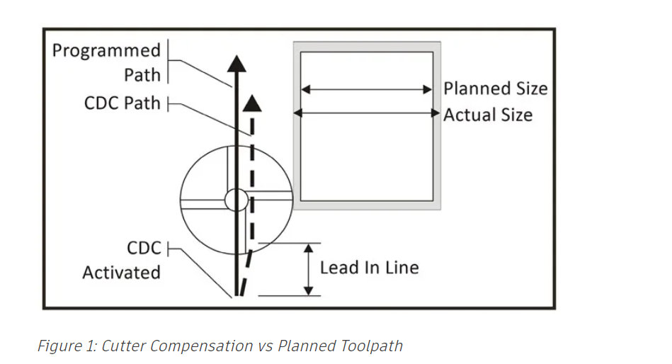
- The toolpath centerline follows the feature geometry. The output code includes a G41 (right comp) or a G42 (left comp), shown below in Figure 3, to offset the tool by the tool radius from the Diameter Offset Table in the machine control. For example, a ¼” tool should have .250 listed in the diameter offset table in the machine control. The output code also includes a G40 to cancel the compensation when the tool path is complete.
- Independent of the diameter of the tool used to cut the material.
- Used when you run both CAM and manual G code on a machine, the Diameter value in the machine offset table is used. Note that the lead in lines must be at least the radius of the tool to apply the compensation correctly. I.e. for a 6mm tool, lead in should be 3mm.
-
Wear
- The toolpath centerline outputs offset from the feature geometry by the radius of the selected tool. The difference is that the diameter in the offset table in the machine control is typically set to zero or the small difference between the programmed tool diameter and the actual measured diameter.
- Most shops that strictly use CAM software to generate toolpaths use “Wear” compensation, as there is more flexibility with smaller lead in/outs. If your ¼” diameter tool measured .251” and your tool offset table had a 0.001” diameter you would only need a 0.0006” lead in/out to turn on/off your cutter comp. This allows you to get into smaller pockets and other confined areas.
- Setting Tool offset
-
Tags: Machines Milling Tormac 15L CNC lathe Feeds and Speeds
-
tags Milling Fabrication
-
Way to kill endmill
- Choosing end mills with coating for dedicated work material is better. an Aluminum Titanium Nitride (AlTiN) coating increases hardness and temperature resistance in ferrous materials, but has a high affinity to aluminum, causing workpiece adhesion to the cutting tool. A Titanium Diboride (TiB2) coating, on the other hand, has an extremely low affinity to aluminum, and prevents cutting edge build-up and chip packing, and extends tool life.
-
tags Engineering Fits and Tolerances Measuring Instruments Milling Turning
-
tags Milling Turning Fabrication
-
tags Metal Working Milling Turning ProtoTrak Mill DPMRX2 Tormac 15L CNC lathe
- tags Tormac 15L CNC lathe CNC MillingTurning Archive ProtoTrak Mill DPMRX2

Notes mentioning this note
Archive
When a Note reaches a significant size they are indexed into the Archive. This is the only place where a...
Deckel Maho DMU 60T
tags Milling Fabrication Resources Heidenhain Mill plus IT manual German Heidenhain Mill plus V600 Manual Eng CNC coding guide Millplus...
Endmill
tags Milling ProtoTrak Mill DPMRX2 Basics of Endmill Way to kill endmill Choosing end mills with coating for dedicated work...
Engineering Fits and Tolerances
tags Milling Turning Machining Measuring Instruments Resources NPTEL Design and Manufacturing IITB limits and Fits Fundamental deviation of shafts Indian...
Machine Design
tags: Robotics #Mechanical Machines Fabable Machines Linkages Resources Theory Basic Machines US Navy guide to basic machines like levers, gears....
Machines
tags Machine Design Machines ZUND Digital cutting machine Roland MDX20 Small format precision milling machine. Omax Waterjet Machining center Abrasive...
Metal Cutting Guide
tags Metal Working Milling Turning ProtoTrak Mill DPMRX2 Tormac 15L CNC lathe Resources Modern metal cutting A Practical guide Sandvick...
Milling
tags ProtoTrak Mill DPMRX2 Milling Machine Endmill Feeds and Speeds Desktop Mills Deckel Maho DMU 60T Resources Student shop pratt...
ProtoTrak Mill DPMRX2
tags Milling Cutting Tool Tool Inserts Resources Trak DPMRX guide University of Wisconsin Detailed guide. DPMRX manual Prototrak Brochure Trak...
Tool Inserts
tags Tormac 15L CNC lathe CNC MillingTurning Archive ProtoTrak Mill DPMRX2 Resources Sandvick Metal cutting Knowledge base Tool geometries Lathe...
Tormac 15L CNC lathe
tags CNC Tool Inserts Turning Resources Tormac Lathe tooling guide Lathe Tooling basics Sandvick Cutting speed guide Hard turning Horsepower...