Tool Inserts
- tags Tormac 15L CNC lathe CNC MillingTurning Archive ProtoTrak Mill DPMRX2
- Resources
- Tools
- Materials
-
Tool coatings
- Tool coatings Harvey tools
- The designation “TiAlN” is used for Ti-Al nitride coatings where the aluminum content is ≤ 50 atomic percent. “AlTiN” is used when the aluminum content is > 50 atomic Prozent.
-
Coatings
- Source
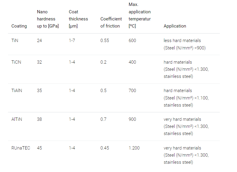
- Titanium Nitride TiN coatings with nitrogen being carrier, amber-gold colour, developed in 70s were first applied on HSS tools to improve thermal characteristics, 4-5 micron thick, they remain most common. Vickers hardness of up to 2,100. This coating has a low coefficient of friction (0.4) and an operating temperature of approximately 1,100 degrees F.
- TITANIUM CARBONITRIDE (TiCN) TiCN is a titanium-based coating with carbon added to it. Bbluish-grey in color and has a Vickers hardness of up to 3,000. Operating temperature of approximately 750 degrees, Collant needs to be applied to prevent premature wear. Only used on soft metals like Aluminum where heat is not an issue. Better hardness and improved wear conditions.
- TITANIUM ALUMINUM NITRIDE (TiALN) typically violet-grey in colour. TiAlN has a Vickers hardness of 3,500, the highest of any of the four common titanium-based coatings. It has an operating temperature of approximately 1,470 degrees. It has a slightly higher wear resistance than AlTiN. TiAlN can be used to easily machine up to a 45 Rockwell with cobalt-based high-speed steel or a 50 Rockwell with a carbide substrate.
- ALUMINUM TITANIUM NITRIDE (ALTiN) with aluminum making up around 60 to 65%, titanium 30%, a blue-violet, purple colour. Has a Vickers hardness of 3,300, making it slightly softer than TiAlN. It has an operating temperature of approximately** 1,650 degrees.** It has the highest thermal capability of these coatings, such as the machining of titanium and heat-treated steels up to 62 Rockwell C. Can be used for heat-treated materials, and typically it is seen in the die and mold industry.
-
Carbide
- Carbide tools are harder than HSS but also brittle.
- They need a constant chip load even if they are heavy and no fast moves.
- They are vulnerable to thermal shocks, you either run them dry or flood cool them.
-
Tool coatings
- Notes
- Tradeoff between strength and versatility, the larger point angles like the 80 deg and round inserts are the strongest, 35 and 55 deg diamond provide fine detailing.
- Trigon inserts have 6 cutting edges, yet have the strength of 80deg diamonds which have only 4 cutting edges.
- Inserts are molded or ground, molded are widely used and economical. Ground are used when exact cutting edges are needed and indexability is highest.
- Round inserts are the most cost-effective method for removing large amounts of material and having better tool life.
-
Tool life
- Using a CNMG,CCMT 80deg insert with a turning and facing tool -5deg led angle is bad for tool life. When milling or turning, switching to a postive lead angle, no only thins the chip but also spreads the cutting force over a greater length of carbide, which reduces failure modes.
-
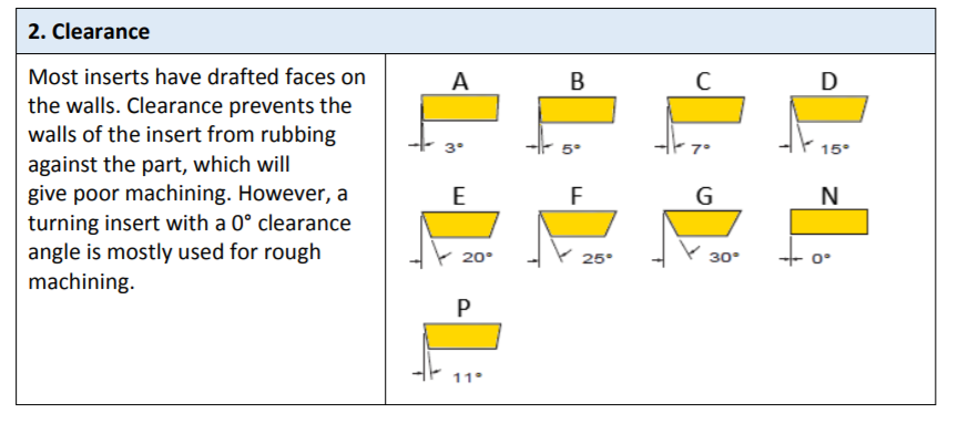
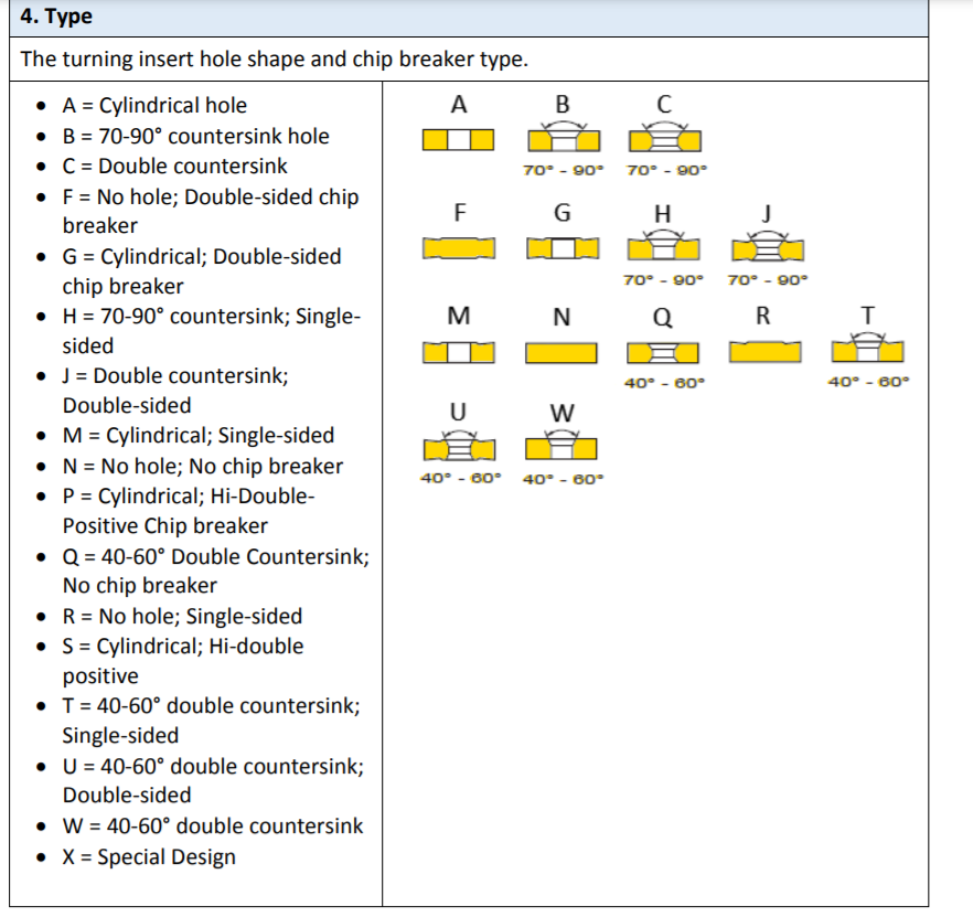
ANSI Designations
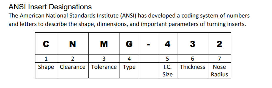
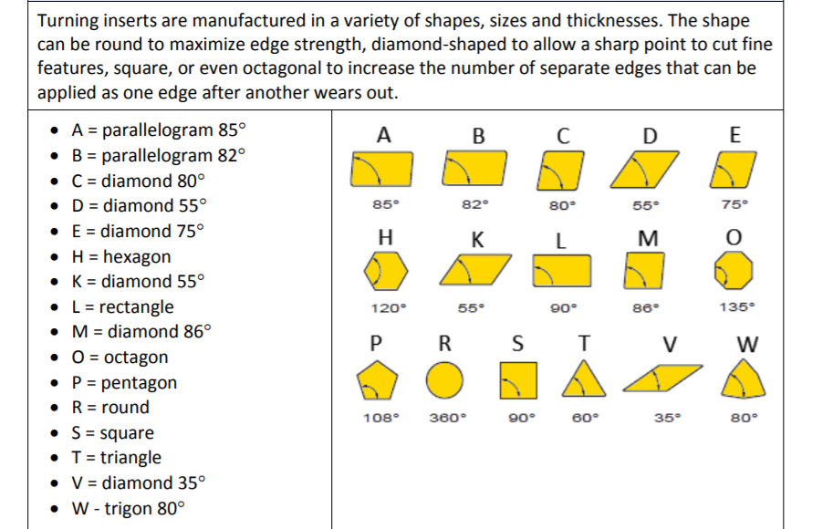
- Inserts with large point angle like C and W are used for rough turning as they have better strength and inserts with small point angles like V, D are used for finish turning and fine detail.
- Large point angle: Stronger cutting edge, Higher feed rates, Increased cutting forces, Increased vibration.
- Small point angle: Weaker cutting edge, Increased access to part details, Decreased cutting forces, Decreased vibration


-
Tool geometries
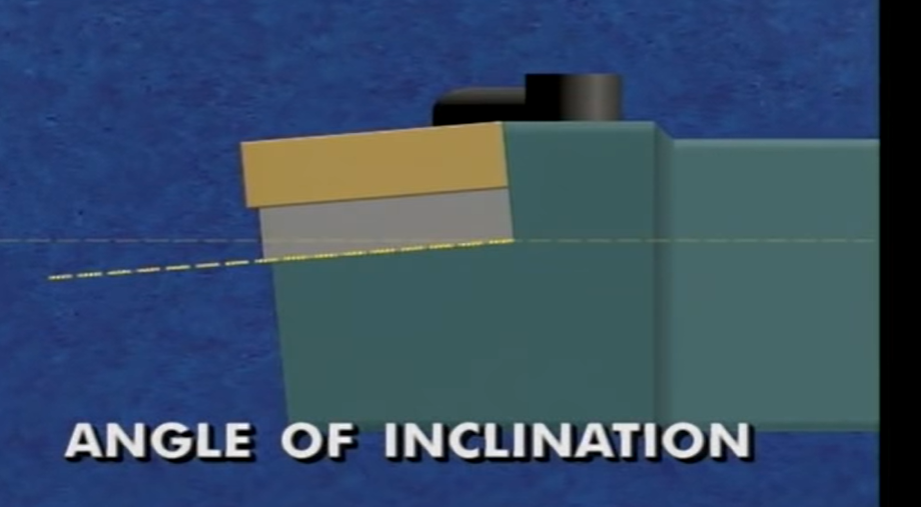
- Angle may be positive, negative or neutral.
- Relation of the cutting edge to the cut. may be positive, negative, neutral.

- Effective rake is a combination of the tool holder angle of inclination and the effective rake built into the insert.
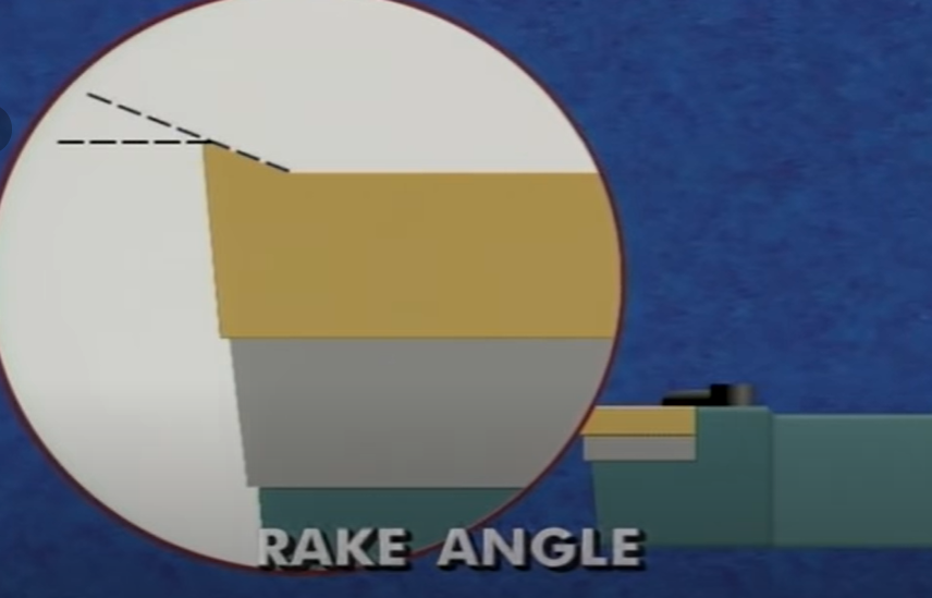
- The largest influence on chip flow is the top/back rake angle it is the imaginary line between the top of the tool and the centerline of the material.
- A positive top rake angle tool cuts freely and requires less power. A negative top rake tool is stronger but more cutting forces and require more power.
- For cast iron, a negative or neutral top rake is preferred for rough turning.
-
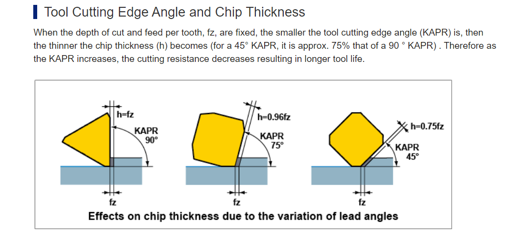
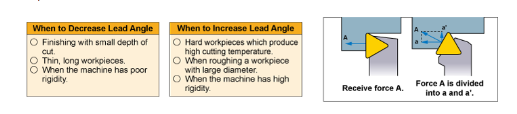
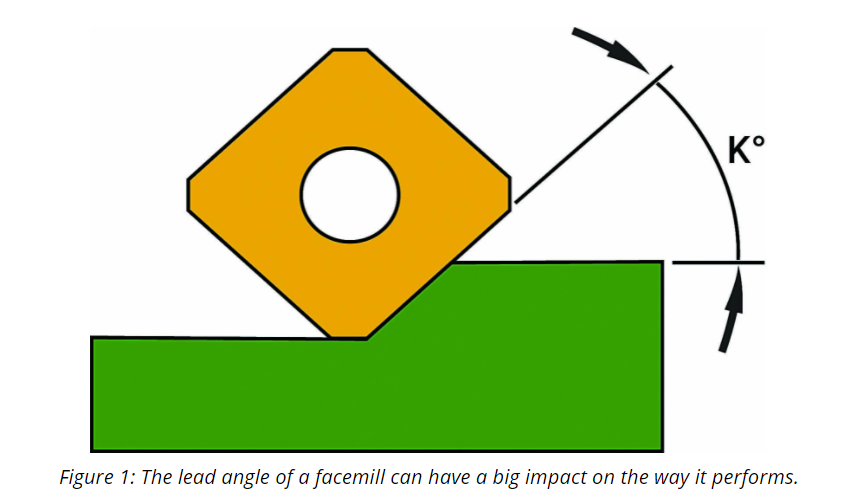
Lead angle
- Lead Angle and effects
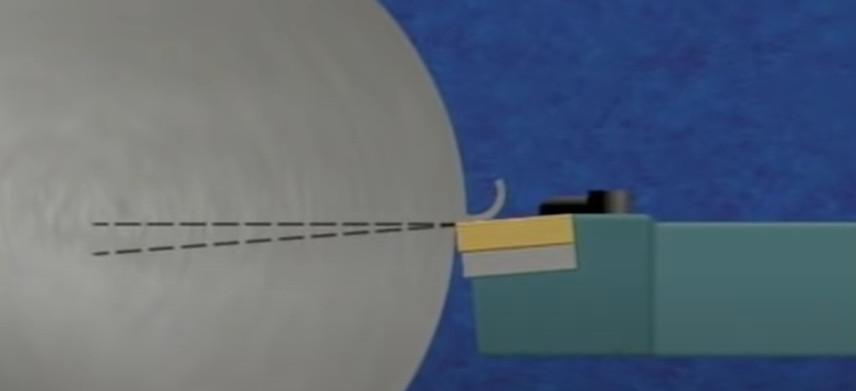
- The Lead angle the angle at which the primary cutting edge enters the work piece.
-
Milling

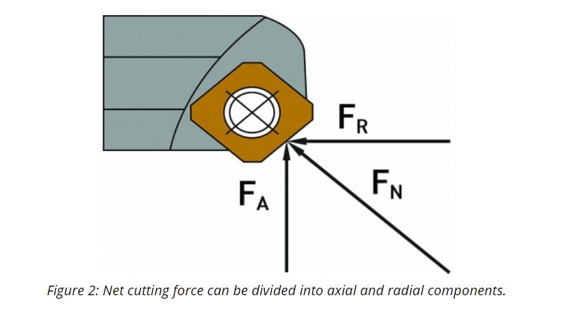
- We want to minimize the radial forces causing the tool to deflect, the machine can handle the axial forces trying to push the tool up. But there is an equivalent force pushing down on the work, so the work holding must be rigid enough.
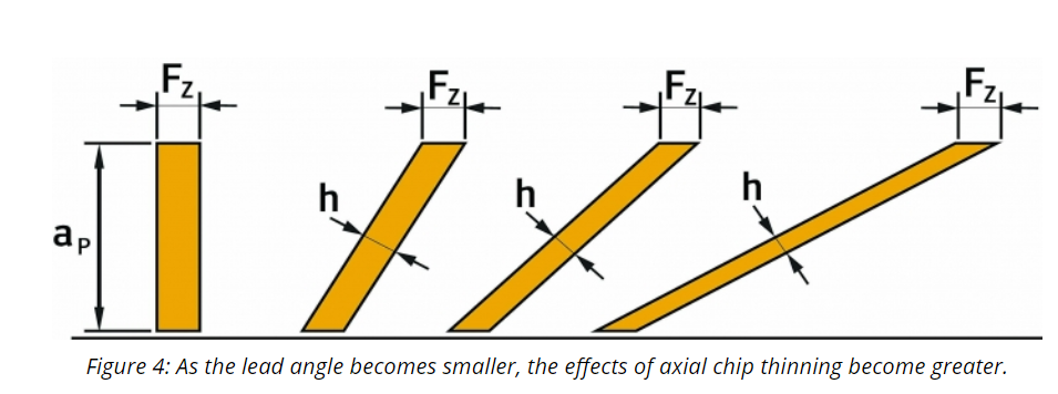
- The chip thickness should adhere to the manufacturer specs, this means as the lead increases so should the advance per tooth feedrate to match the chip thickness.
- If proper chip thickness is not maintained then causes tool to rub, and thin chips don’t have the ability to carry heat away from cutting surface.
- The main benefit of using a 90 deg face mill (shoulder mill) is that it can provide a square shoulder.

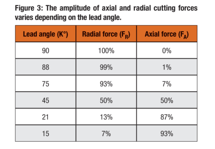
- Face mills with lead angles of 15° generally are considered high-feed mills. The lead angle is so extreme that cutting forces and axial chip thinning become one-sided. 93% of cutting force is in the axial direction, which is directed up through the spindle. This makes a 15° lead cutter quite stable even with long overhangs or when machining deep pockets. Only 7% of cutting forces are in the radial direction.
-
Turning

- In turning a 15-30 deg lead angle is often used. This reduced the cutting forces, thins the chip and reduced pressure on the edge.
- When turning a shoulder tool should have a 0 to -5 deg lead angle. Boring bars need a 0 deg lead angle to minimize forces and reduce deflection.
- The finish of the cut is a combination of the tool nose radius and the feed per revolution.
- A larger tool nose radius is stronger and resists heat, but also increases the radial forces.
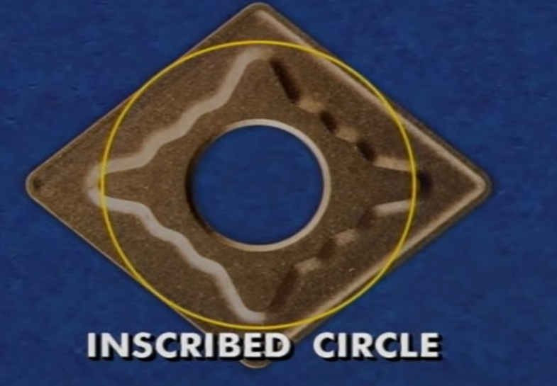
- The inscribed circle is the largest circle in the tool and determines the size of the insert.
-
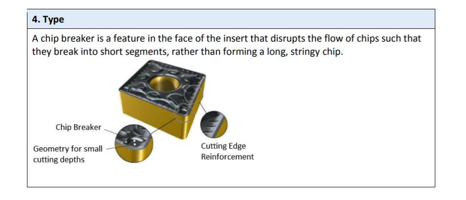
Chip breaking
- Relation between feed rate, depth of cut, chip breaker design.
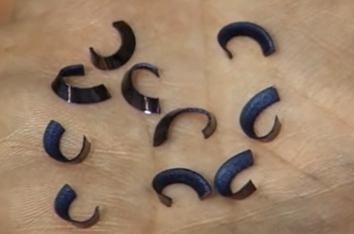
- Ideal type of chips, easy to dispose and occurs when the tool is cutting the most effficient.
- The Hay chip is undesired, the chip breaker is too wide and shallow. Switch to different design, move chip breaker closer, increase the feed rate.

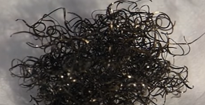
- Corrugated chip, chip breaker is too narrow and deep, thus crowding the chip, promote excess wear
- A steel chip absorbing heat leaves the work piece light golden colour and then turns blue. But the chip immediately starts turning deep blue then excessive heat is being generated.
-
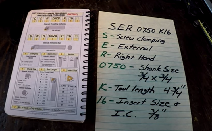
Threading #Tormac 15L CNC lathe
- Threading Sandvick
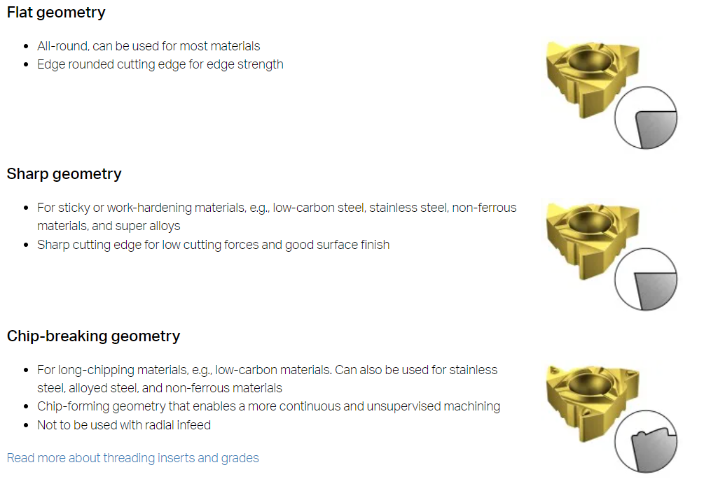
- Threading tool geometry
- Sumitools Guide to threading
- Isometric thread chart

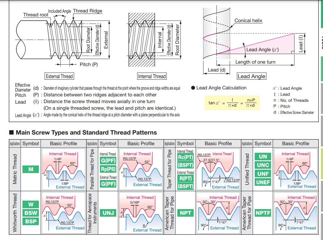

- Max depth of cut should be limited to 0.5mm

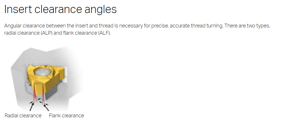

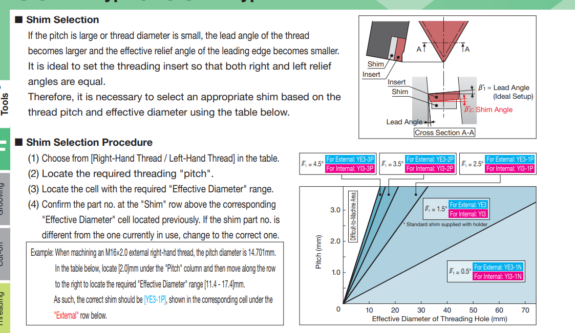
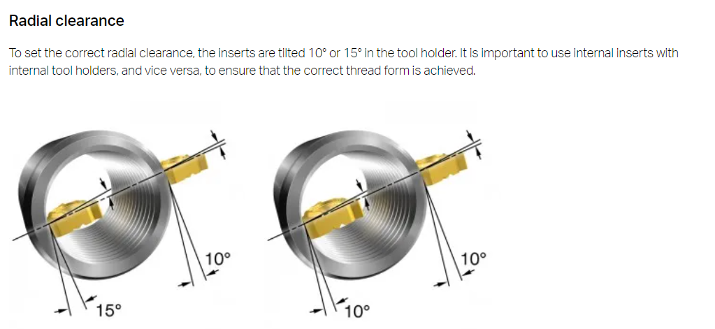
- The flank clearance is important as the insert needs to be tilted to match the helix angle of the thread so that symmetrical clearances are there on both sides of the thread.
- tags CNC Tool Inserts Turning
Notes mentioning this note
Archive
When a Note reaches a significant size they are indexed into the Archive. This is the only place where a...
Milling
tags ProtoTrak Mill DPMRX2 Milling Machine Endmill Feeds and Speeds Desktop Mills Deckel Maho DMU 60T Resources Student shop pratt...
ProtoTrak Mill DPMRX2
tags Milling Cutting Tool Tool Inserts Resources Trak DPMRX guide University of Wisconsin Detailed guide. DPMRX manual Prototrak Brochure Trak...
Tool Inserts
tags Tormac 15L CNC lathe CNC MillingTurning Archive ProtoTrak Mill DPMRX2 Resources Sandvick Metal cutting Knowledge base Tool geometries Lathe...
Tormac 15L CNC lathe
tags CNC Tool Inserts Turning Resources Tormac Lathe tooling guide Lathe Tooling basics Sandvick Cutting speed guide Hard turning Horsepower...