Machine Design
- tags: Robotics #Mechanical Machines Fabable Machines Linkages
- Resources
- Theory
- Basic Machines US Navy guide to basic machines like levers, gears.
- Fundamentals of Design MIT precision Engieering Research group, Design principles
- Fundamentals of Design videos
- Linear actuation design guide HIWIN design guide
- Align Linear guide ways
- CNC machine setup and alignment
- Dover Motion control Handbook Various motion control topics
- MIT OCW Engineering Drawing fundamentals MIT
- Kinematic Couplings MIT PERG MIT
- https://www.machinedesign.com/mechanical-motion-systems Mechanical motion systems learning
- Linear motion tips Guides on linear motion stage, racks, Plastic bearing Machines
- Motion Control tips Guide design, controllers, Machines
- Machine thinking Origins of precision
- Engineering Whitepapers whitepapers design
- Radlines CNC vector lines generator
- European Steel Design Educational Program Steel
- Cad
- Builds
- Documents
- Opensource machines How to make basic machines, old documents and techniques
- Essential machining skills #Tormac 15L CNC lathe Milling
- Machine design
- Design of Machinery
- saintsmart grbl laser mill setup and test
- Maintanance
- Fabrication Techniques
- Notes
-
Aligning CNC machine axes
- Source
- Uncertainty ratio, where if you want to calibrate something to one value, you need at a minimum measuring device that can go up to four times the value, eg for +- 1mm you need a resolution of 0.25mm. A 10 to 1 ratio is better to solve cumulative errors in the system.
- The industry standard minimum TUR is 4:1, the standard must be at least 4 times more accurate then the unknown you are trying to calibrate. Ideally a 10:1 is much better but hard to achieve as accuracy increases.
- You can use a ball bar or a laser alignment system to verify the accuracy of the motion about the axes.
- The first thing to do is to check your table to see if is Flat, if it’s not then do not surface the table, this will hide any underlying problems in the machine. Many make the mistake of tramming the spindle to the table as the first step, but it should not be.
- After we make sure the table is flat. We need to check if they run straight. We check in the X, Y axes to make sure the table is running true.
- Once the table is flat and the axes are moving true, we need to** check if it’s square**. We want to make sure the plane of motion in X is perpendicular to the plane of motion in Y as if it’s not then features we mahcine will be out of square.
-
Step 1 Leveling
- The main purpose of leveling is not to make you machine dead level, it is to take out any twist in the frame and the casting.
- Use a machinist level to get the casting of the machine level.
- Run table across the short Y-axis column to make sure that there is no twist in the table when you move the gantry. Adjust the leveling feet to take out any twist in the casting.
- Run the table across the X-axis to see how much deviation is there, for Box type and linear gantry type machines about 30 arc seconds of deviation is common.
- The first thing is to level the machine, do not use a spirit level, use a machinist level which is accurate up to 10 arc seconds.
- A degree is 1/360 of a turn and** one arc minute is 1/60 of a degree** and one arc second is 1/60 of an arc minute and 1/3600 of a degree.
- When leveling, remove the way covers and level the machine using the precision ground surfaces on the casting. Do not put the level on the table and level the machine, this should be the last step. If its an old machine then the levels are sensitive enough to pick up the wear on the table.
- The precision surfaces on the castings do not wear as they are not touched in operations.
- The next we want to check for unwanted rotations in the two axes during motion called the Abbe Error
- Abbe error Dover Motion
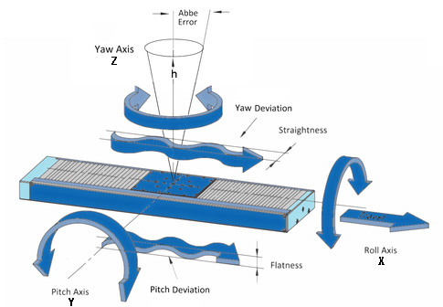
- Abbé errors are caused by the combination of angular errors in the motion system and the offset between the point of interest (tooling, load, etc.) and the origin of the error (screw, guideway, etc.). Errors in roll, pitch, and yaw typically result from inaccuracies in the guide system, but mounting surfaces and methods can also be sources of angular errors. For example, mounting surfaces that are not precisely machined, components that are not sufficiently fastened, or even varying rates of thermal expansion between the system and its mounting surface can all contribute to angular errors greater than those inherent in the linear guides themselves.
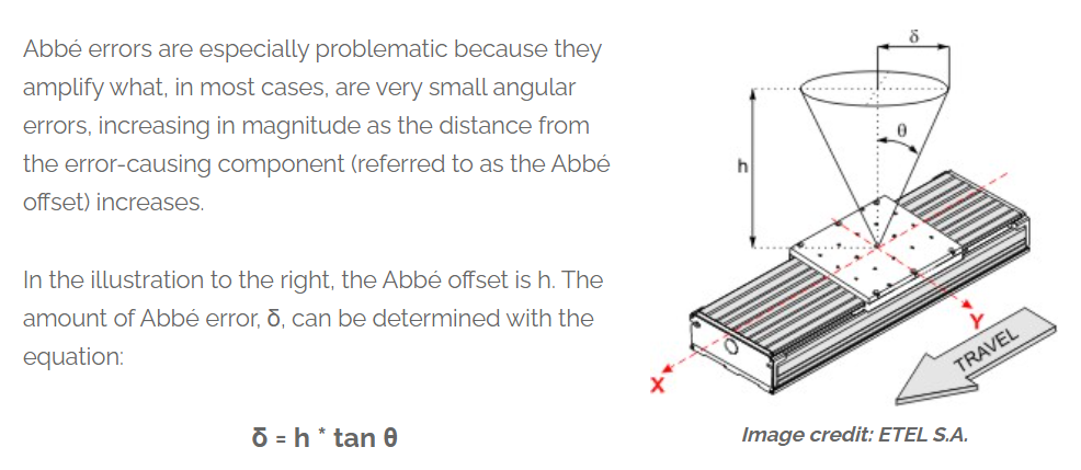
- The farther the load is from the cause of the angular error the greater the deviation will be. The best methods for minimizing Abbé errors are to use high-precision guides and to ensure that mounting surfaces are sufficiently machined so they don’t introduce additional inaccuracies to the system. Reducing the Abbé offset by moving the load as close as possible to the center of the system will also minimize Abbé errors.
- Abbé errors are most accurately measured with a laser interferometer or other optical device that is completely independent of the system.
- Using the feet of the machine, you want to minimize any twist in the frame that can show up in the casting (y axis).
- Use the level to find the twist in both axes, this determines the max accuracy that you can get with the machine, the error will be small in the center, but as you move farther away and depending on how high the part is there will be a huge error at the top.
-
Step 2 Table parallel to Motion
- Once the casting and guide ways are level, we need to make sure the table is parallel to the motion of the X,Y stages.
- If the table is tilted in any direction, then there will be difference in the z height when the part is machined across the table.
- The way to make sure the table is level is to use a dial indicator in the z axis with a precision straight edge and run it across the table to note the deviation, there might be some of the previous abbe errors, or it could be the table is worn out in certain places.
- Once you determine the level, do not surface the table this will only mask the underlying problems. If you have a boxway machine, you can adjust the gibs on the machine to make sure the axes are aligned properly. If you have linear guides, then the trucks/bearings have precision ground surfaces on them between which you can put a shim to make the table level. The purpose of the shims are to bing the table flat when it was originally built.
-
Step 3 Straightness of X and Y
- As the table is moving along the axis, is it moving in a straight line or like a snake.
- You need a precision straight edge/square, place it on the table and align it to one of the axis with a dial indicator, as you move the length of the travel, check the dial indicator to see if there is movement.
- If there is movement, if you have a machine with linear guideways then remove the covers and loosen the bolts for the trucks which hold the table.
- Along the length of the rail there will be setscrews at repeating intervals, loosen the SHCS that hold the rail to the casting and adjust the setscrews as needed to press on the rail against the machined reference structure.
- Hang a dial indicator form the table and make the rail straight with itself, then bring out the straight edge and set the remaining.
- Once the master rail is set, hang an indicator to the table and work on the second rail. When tightening the SHCS, you must use a torque wrench as if you over tighten them they will crush the rails.
-
Step 4 Squaring the X & Y
- The straightness measures how straight the axes move, the squareness mean how perpendicular the two axes are, if they are not then when you are doing long jobs, the result will be a parallelogram.
- Use a precision square and align it to one of the axes, run the dial indicator on the perpendicular face to check the deviation on the second axis.
- If you have a linear slide machine, then you need to loosen all the bolts from the trucks, this will allow the saddle to move free, and whichever way you want to move the saddle.
- Place shim stock there, tighten the setscrews that push the truck to the saddle reference edge, this will be the master truck, and do the squareness again to check and repeat process.
- Any time you make an adjustment, you have to start back at step one to make sure the machine is level. It take a while to set everything up, each time you progress a bit deeper and deeper.
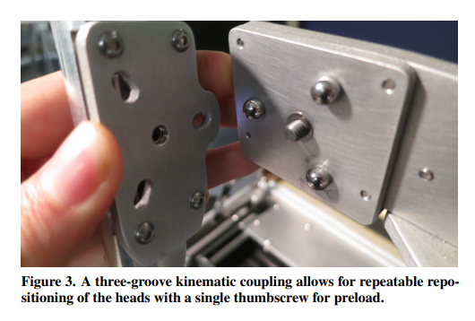
- #kinematic Joints
-
Rack and Pinion
- A pinion of about 20 teeth is mathematically the optimum in terms of tangential force and system backlash. A larger pinion provides more backlash, a smaller pinion can transmit lower torques and has a higher wear.
- Theory
-
tags #Machine Design CNC #Linear Stages
-
tags: #Mechanical #Compliant mechanism #Machine Design
-
tags: #Machine Design MIT
-
tags: Machine Design MIT design #Mechanical
-
tags: #Machine Design CNC #Linear Stages Bearing
-
tags: CNC Machines #Machine Design
-
tags: #Machine Design design Mechanisms
-
tags Machine Design
-
tags: #Mechanical Machines #Machine Design Linkages
-
tags Machining Machine Design
-
tags MIT Machine Design
-
The secret life of components design #Design for Prototyping #Machine Design #Product Design
-
tags: Mechanisms #Machine Design
-
tags Machines #Machine Design #3D Printing
-
tags CNC Machine Design
- tags #Machine Design
Notes mentioning this note
3D Printing
tags: CNC Machines MTM Marlin Resources Edith Engineer steppers 101 Common 3D printing troubleshooting Common problems with examples and solutions....
Compliant mechanism
tags: Machines CNC MTM Flexure Resources Flexible Research group UCLA Axiomatic design theory for systems Nam suh Quality through axiomatic...
Design for Prototyping
Introduction What is a Design? A design is an iterative process to find a solution to a defined problem falling...
Fundamentals of Design
tags: Machine Design MIT design #Mechanical Resources Fundamentals of Design video Meddevdesign MIT Fundamentals of Design Simple beam bending theory...
G code
tags CNC Machines Resources Random G code gererator #Machine Design Gcode primer Linux cnc g code overview G code flow...
Machine Design
tags: Robotics #Mechanical Machines Fabable Machines Linkages Resources Theory Basic Machines US Navy guide to basic machines like levers, gears....
Machines
tags Machine Design Machines ZUND Digital cutting machine Roland MDX20 Small format precision milling machine. Omax Waterjet Machining center Abrasive...
Mechanisms
tags: #Mechanical Machines #Machine Design Linkages resources Softwares Linkage design and simulator tutorial Linkage design and simulator Mechanism design Software...
Milling
tags ProtoTrak Mill DPMRX2 Milling Machine Endmill Feeds and Speeds Desktop Mills Deckel Maho DMU 60T Resources Student shop pratt...
Precision machine design
tags MIT Machine Design Resources Principles and techniques for designing precision machines Hale Layton Alternate Design and testing of a...