Circuit Design
- tags design Electronics Mechatronics Mechatronica M10V pick and place Eagle CAD
- Resources
- Notes
-
Pull up Resistors
- Sparkfun pull ups
- When reading the input state of a pin, if it is not connected to ground, then it can be in a floating state. To avoid this, pins are usually pulled up or down, depending on whether it is connected to VCC or ground.

- The value of R1 is chosen such that a small amount of current flows through it, if its too low it could cause a short. A low resistor value is called a strong pull-up (more current flows), a high resistor value is called a weak pull-up (less current flows).
- Usually a resistor of the order of 10K is used as a pullup.
- The value of the resistor controls two things,
- How much current flows through the button and to the ground.
- The voltage on the input pin.
- The lower the resistance, the more power is used when the button is hit, but this should not conflict with the second condition.
- The pull up resistor should be an order of magnitude (1/10) the input impedance. The input impedance represented by R2 of most micro controllers can vary form 100k-1MΩ. R1 and R2 divide the voltage and it needs to be above a certain value to register as a high state.
- Another thing to note is that **the larger the resistance of the pull up is used the slower the pin is to react to voltage changes. ** The system that feeds the input pin is essentially a capacitor coupled with the pull-up resistor, thus forming an RC filter, and RC filters take some time to charge and discharge. This is why you will often see 1k to 4.7KΩ resistors on USB signal lines.
-
Resistors and Forward voltages of LEDs
- All about LED Adafruit
- In any loop of circuit the voltages must balance, Kirchoff’s law, the amount generated = amount dissipated
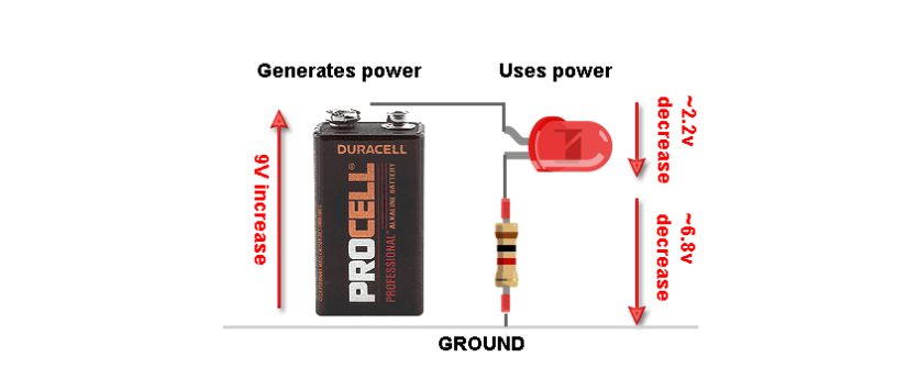
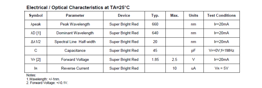
- LEDs have a forward voltage which is the voltage they drop when operating at a certain current usually 20ma. Most LEDs have a forward voltage of about 2.2V so if it’s connected to a 5V supply then the resistor must absorb the 2.8V to make the loop equal.
- If we choose a resistor with 1000ohm then the current through it is V/R = 6.8/1000 = 6.8 mA. The current determines how bright the LED is and most are rated for If=20mA
-
Voltage Dividers


- The resistor closest to the input is R1 and voltage out Vout will be across the R2. The ratio of R1 to R2 determine the output voltage.
- Equation can be proved by Ohms law, assume same current in both the resistors, since resistors are in series add them to one unit, then Vout= IR then substitute Vin for IR.
- If R1 =R2 voltage will be half the input. If R1» R2 then output will be close to zero and conversely if R2» R1 then output will be equal to input.
- Applications

- Potentiometers act like voltage dividers if we take the output from the middle.
- Reading Resistive sensors
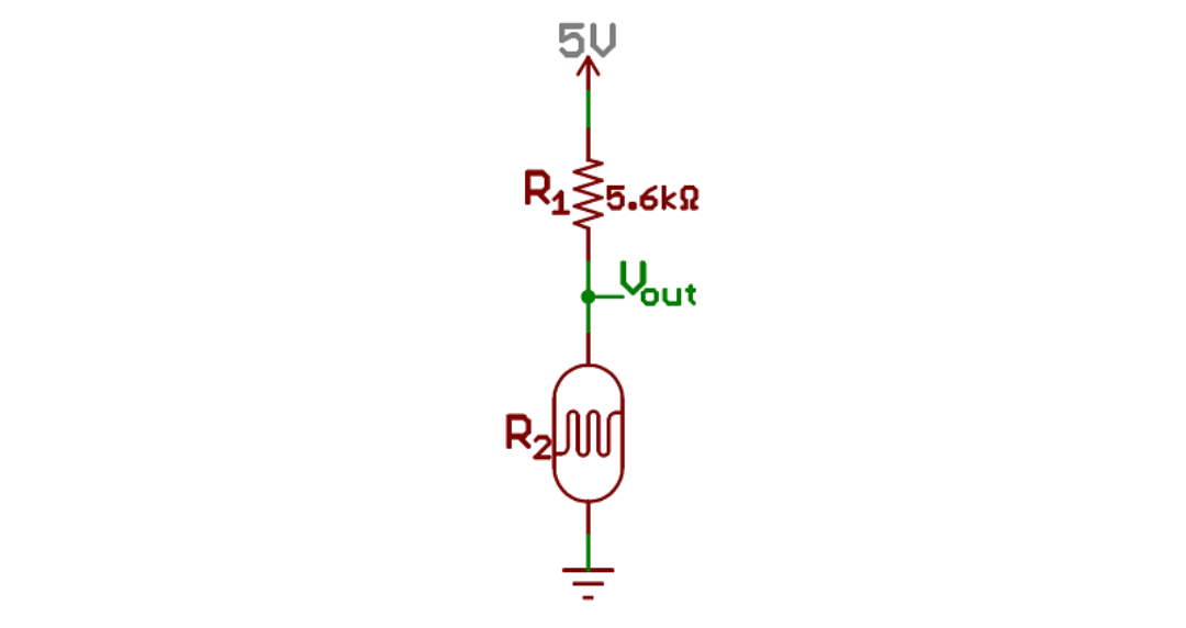
- Microcontrollers with ADC can read voltages well but cannot measure resistance. Many sensors are simple resistive devices like a photo cell which varies from 10K to 1K from light to dark. If we add a 5K resistor to the circuit we can measure a wide range of voltage and back work the resistance.
- Level Shifting
- Voltage dividers can level shift from higher voltages to lower ones like 5V to 3.3V but are unidirecitonal.
- Dividers should never be used to deliver power to a load.
-
Analog to Digital Converter ADC
- It converts an analog voltage to a digital number. ADCs can vary across microcontrollers some have 10-bit ADC meaning it has the ability to detect 1,024 (2^10) discrete analog levels. Some microcontrollers have 8-bit ADCs (2^8 = 256 discrete levels) and some have 16-bit ADCs (2^16 = 65,536 discrete levels).
- The most common technique uses the analog voltage to** charge up an internal capacitor and then measure the time it takes to discharge across an internal resistor.** The microcontroller monitors the number of clock cycles that pass before the capacitor is discharged. This number of cycles is the number that is returned once the ADC is complete.
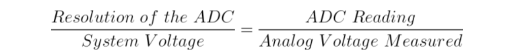
- The ADC reports a ratiometric value. This means that the ADC assumes 5V is 1023 and anything less than 5V will be a ratio between 5V and 1023.

-
Filter Capacitors
- Filter capacitors
- Capacitors work as analog filters because they are reactive components whose impedance is a function of frequency. Capacitors which filter out a frequency is called a filter capacitor, the most common being to filter out DC in certain circuits.
- A 1Hz & 100KHZ signals flow throughout a resistor with equal resistance. Reactive devices like capacitors that offer high resistance to low-frequency signals and low-resistance to high-frequency signals using the formula like XC= 1/2πfc. (capacitors in series)
- In power supply circuits, this capacitor can be calculated to ensure the least ripple at the output. The formula is C = I / 2f Vpp
- From the equation above, ‘I’ is load current, ‘f’ is i/p frequency of AC and ‘Vpp’ is the minimum ripple that may be acceptable.
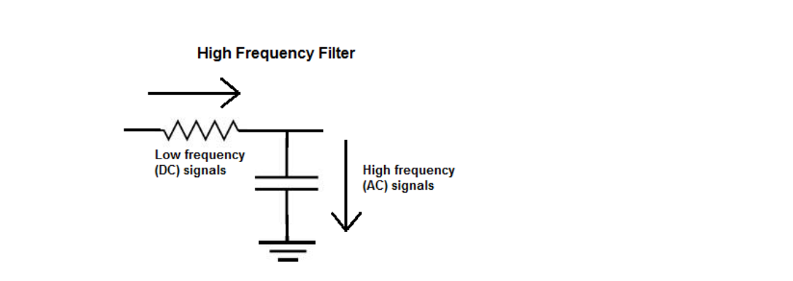
- The capacitor is connected in parallel forming a High-frequency filter. The current will take the least resistance path and capacitors provide least resistance to high frequency.
- For my experiment, I hooked up a 100nF (0.1µF) ceramic capacitor in series with a function generator to see which frequencies the capacitor blocked or attenuated and which frequencies went through unimpeded. It turns out the capacitor blocked only very low-frequency signals, between 0 Hz to about 0.5Hz, or 500 mHz. It will attenuate signals a little from about 0.5Hz to 3Hz. But after that, it no longer attenuates signals above 3Hz.
-
Line Capacitors
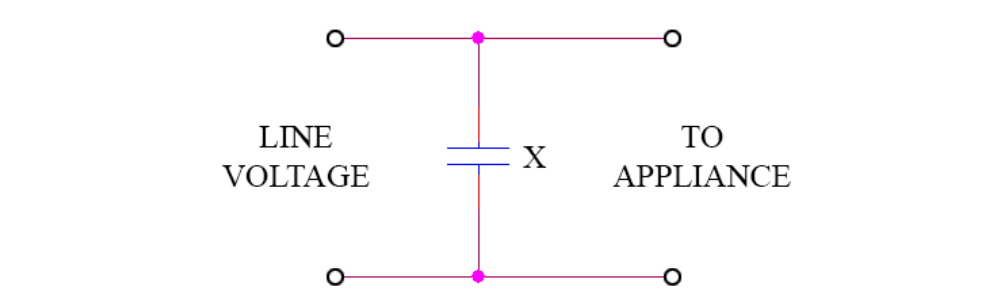
- These are used to attenuate high frequency noise form the input lines of power supplies. The capacitor acts to short circuit the high frequency signals and only let the DC signals pass thorough.
- In the range between 1µF and 10µF, and are made from polypropylene for high frequency applications, since polyester capacitors can overheat.
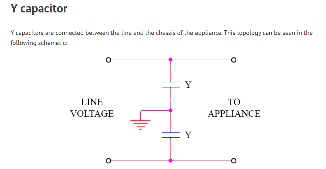
- Used when the appliance has a grounded chassis. The chassis itself can act as an electromagnetic shield (Faraday cage) which protects the appliance from outside RF interference. In case of capacitor malfunction, this topology is potentially more dangerous to the user.
- A wide range of capacitance values, between 0.001µF and 1µF. Metallized paper and film capacitors are preferred over ceramic capacitors for Y capacitor applications due to their stability, higher capacitance values and self healing properties, as well as the fact that the failure mode of metallized capacitors tends toward open circuit, while the failure mode of ceramic capacitors tends towards short circuit, which is potentially more dangerous to users.
-
High Pass Filter

- A high pass filter allows high-frequency signals to pass through while blocking lower frequencies. They can be made by using resistors with either capacitors or inductors.
- A capacitor placed in series will offer little resistance to high-frequency signals while blocking low-frequency (DC) signals. These are called RC filters.
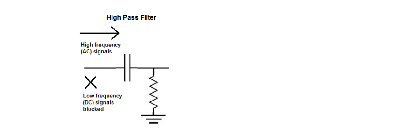
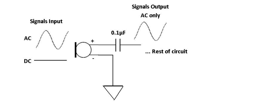
- This type of capacitor also functions as a coupling capacitor because it couples the AC signal from one part of a circuit to another, while blocking the DC.
- They are used in microphones which need DC power to turn on and operate but the output of the microphone is the audio signal which is an AC signal that needs to sent out. The DC is for powering on the systems and should not be mixed with the output.

- So the formula to calculate the frequency of an RC circuit is, frequency= 1/2πRC. Doing the math, we get, frequency= 1/2πRC= 1/2(3.14)(1000Ω)(0.00000001F)= 15,923 Hz.
- Therefore, this RC circuit will pass frequencies above 15,923Hz with barely any attenuation. Frequencies below 15,923Hz will be attenuated. The further away and lower it is from 15,923Hz, the greater the output signal is attenuated.
- A high pass RL filter is constructed by placing the inductor in parallel with the circuit
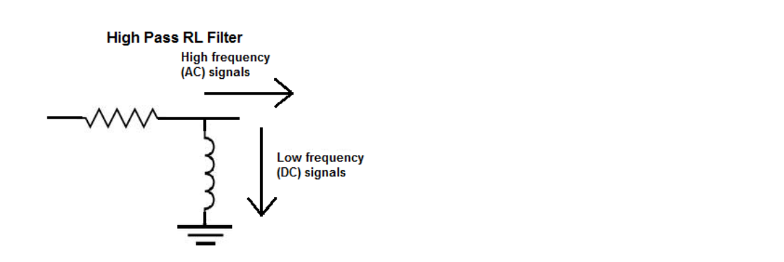
- This works on the principle of inductive reactance, the inductor passes low frequency signal with ease while blocking high frequency signals, since current takes the least resistance path, all low frequency signals are shunt to ground.
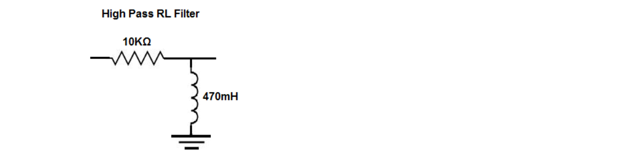
- Since the formula for a high-pass RL filter is f= R/2πL= 10KΩ/(2(3.14)(470mH))= 3,388 Hz, which is approximately 3.39KHz. This means all frequencies above 3.39KHz will be passed through without attenuation, while frequencies below this value will begin to get attenuated. As you get lower and lower and further away from 3.39KHz, there is greater attenuation as the frequency goes down.
-
Why is there a resistor in an RC,RL circuit?
- Since the resistance of the capacitor leads are not known, adding resistors will overshadow them and bring them to a definite value.
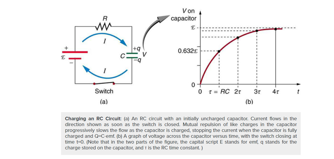
- A resistor impedes the flow of charge, hence a charge-discharge cycle can be known. The time constant can thus be defined.
- The Time constant forms the basis for filtering. **The time constant **is the time required to charge the capacitor, through the resistor, from an initial charge voltage of **zero to approximately 63.2% **of the value of an applied DC voltage, or to discharge the capacitor through the same resistor to approximately 36.8% of its initial charge voltage. (These values are derived from the mathematical constant e 63.2%=1-e^-1
- The time required for the capacitor to be fully charge is equivalent to about 5 time constants or 5T.
- Practically, charging and discharging a capacitor without a resistor will result in a large flow of current, possibly destroying circuit components.
-
tags Circuit Design Electronics Communication protocols
-
tags: Circuit Design
- tags Electronics Circuit Design
Notes mentioning this note
Archive
When a Note reaches a significant size they are indexed into the Archive. This is the only place where a...
Circuit Design
tags design Electronics Mechatronics Mechatronica M10V pick and place Eagle CAD Resources Beginning Embedded Electronics Sparkfun Ultralibrarian parts eagle library...
Eagle CAD
tags Electronics design Circuit Design Resources Autodesk Eagle Tutorials Fab academy Introduction to Eagle CBA Fab Eagle library Fab Eagle...
Electronics
tags: Circuit Design Resources All about Circuits: Electronics Basics Electronics for Geeks Physics Videos by Eugene #Youtube courses watch Electronics...