Mechatronica M10V pick and place
- Resources
- Happy Onam with Mechatronika a short video we did for Onam celebrations with the Mechtronika.
- Notes
-
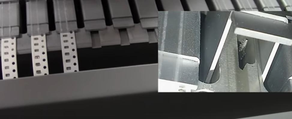
SMD tapes
- You have to match the tape with the feeder or it will not work.
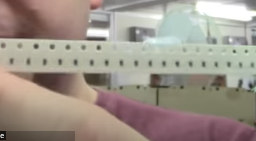
- Holes along the top are called the **sprocket holes **and they are used to advance the tape in the feeder. Also uses the holes to align the tapes into the repeatable position, the distance is 4mm.
- Carrier is the place where the component is sitting. the **carrier pitch **is the distance between components. You need to know the carrier pitch as it sets the **feed rate **of the reel. Feed rate is important as if you advance the wrong increments the components will not be in the same place and the pickup head can not pick it up repeatably.
- The width of the tape is also important, common one is 8mm tape, SOIC comes in 12 mm tapes.
- **Loading the tapes **
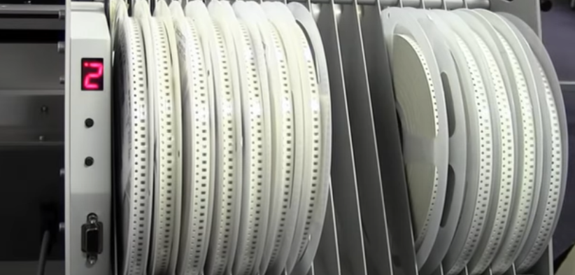
- put the tape on the matching width feeder lane, pull the initial sticky tape back and stick it to the tape. feed the tape through the clasp till you reach the end of the initial sticky tape, pull the tape over the clasp and into the plastic cover winder.
- The advance pin will push the tape forward depending on the feed rate set per lane.
- Press the top button to select the lane and the push the bottom button to advance by one step.
-
Set the feedrate
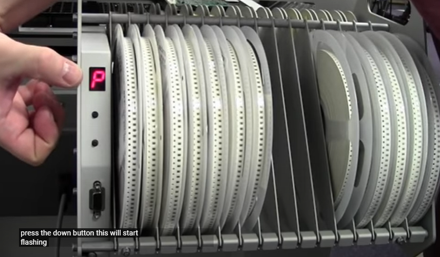
- Press both the buttons, A will be displayed, press the top button, P will be displayed. Press the down button, it will start flashing. this will take us to set the feed rate, press the top button to select the lane. Press the bottom button and a bar will be displayed.
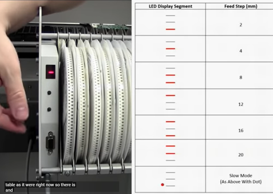
- The distances are standard increments and the bars indicate the positions. Once you select the feedrate, press the upper button, it will go to the lane selection menu, cycle all the way to 0, press the bottom button, a little o will flash indicating that the feed rate is saved.
- If you have more than one feed holder, you want to set the lane address. In order to set the lane address, press both the buttons, A appears, press the bottom button, cycle through the various lane numbers and press the bottom button to set the address. The important thing is that the lane addresses should be unique, you set the various parts in the software and tell it to pick the component form different lanes.
-
Picking up components
- The important thing is to measure the height of the component as it changes from manufacturer. Also measure the length and width.
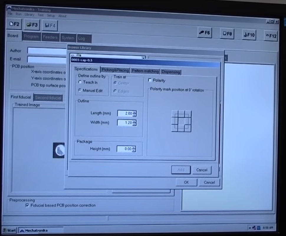
- Go to library in the software and add folder or package, give a standard name like 0805-cap-0.5, package, type, height. Define the length and width and package height.
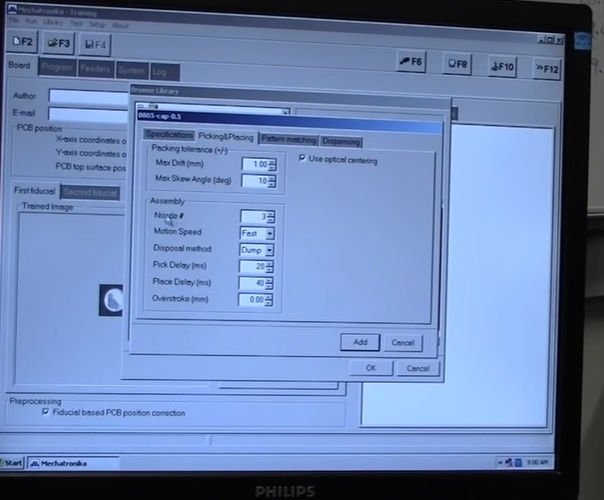
- If the part is in a tape, set the packaging tolerances and the max skew angle. The most important thing is selecting the nozzle size. You want to use the largest diameter nozzle for your part size.
- Pick and place delay is the time the nozzle stays near the component when its picking and placing them.
- Overstroke is how many millimeters you want to push the component into the solder paste. It can squish components down but can cause the paste to spread and create shorts.
-
Workflow for Pick and place machine
- Note- add screenshots
- Add the component to your library, Remember you are adding packages and not individial parts, parts with values come under a single package, eg- 1206 resistor as package and 10k, 49k, 100E are parts.
- Measure your part, length width and height. You can also tech in the sizes with the camera.
- You can use the default pick-up setting, but select a nozzle size that matches your part. You want to use the biggest nozzle the part can accommodate, like for the 1206 package, Nozzle number 4.
- You need to set up a container before you can train the part. You can set up a tape or a Bulk container.
- For a Bulk container, train the top left and bottom right of the container as the pickup position. Set the pickup height to the bottom of the container. For Bulk container the software uses the height set in the part library to define the pickup height of the component.
- Keep one component orthogonal to the axes in the container to train the model. Choose the feeder you have set the parts in and train both the top and bottom models.
- For larger parts like SOIC, you need to train the two corners of the part with the bottom camera.
-
Running a Program
- To run a program, you need to set the board origin in the Board menu.
- You can train the bottom left corner with the machine to set the origin and use measure to set the Z height.
- Additionally fiducial points can be set in the board to correct for any alignment issues in large boards.
- Go to the program tab and right click and add, choose a part from the library and manually teach in the position.
- Press F6 to set the run condition to line by line. Press F12 to start the program, by default which line is selected the program will start from there.
-
Running a CSV file
- A CSV output can be obtained form any PCB design package, it contains the name of the part, the coordinates of the center point, and the rotation.
- Go to program and right click, import csv file. Important, the headers should match the default headers in the mechatronika software.
- Point each of the headers to the respective headers in the csv file.
- If you don’t use the same names in both your design file and in the mechatronika library, you will need to tell the software, what each package is.
- Once you match the packages, you will now need to match the values of the parts inside these packages, again if you use the same name, the software will pick it up automatically.
- Remember that the orientation you teach the part into the software will be the 0 deg rotation of the part, make sure they match in your Design software.
- Next you will be asked to teach in the positions of two components from the list. All the rest of the components are placed relative to this, so do this as accurate as possible.
- Press F12 to run the program, press F6 if you want to run step by step.
-
Things to watch out for
- Measure the parts accurately, especially the height.
- Set the pickup height to the bottom of the tray in bulk components. The system uses the part height to calculate final height.
- Train images under fixed lighting conditions so that they are repeatable.
-
SMD tapes
-
tags design Electronics Mechatronics Mechatronica M10V pick and place Eagle CAD
- Mechatronica M10V pick and place
Notes mentioning this note
Circuit Design
tags design Electronics Mechatronics Mechatronica M10V pick and place Eagle CAD Resources Beginning Embedded Electronics Sparkfun Ultralibrarian parts eagle library...
Eagle CAD
tags Electronics design Circuit Design Resources Autodesk Eagle Tutorials Fab academy Introduction to Eagle CBA Fab Eagle library Fab Eagle...
Electronics
tags: Circuit Design Resources All about Circuits: Electronics Basics Electronics for Geeks Physics Videos by Eugene #Youtube courses watch Electronics...
Machines
tags Machine Design Machines ZUND Digital cutting machine Roland MDX20 Small format precision milling machine. Omax Waterjet Machining center Abrasive...
Mechatronica M10V pick and place
Resources M10V setup Happy Onam with Mechatronika a short video we did for Onam celebrations with the Mechtronika. Notes SMD...
Mechatronics
tags Robotics
J Edward Carryer Stanford
Introduction to Mechatronics J Edward carryer
Pippet Jockey Medical robots